Kinematics and mass
9 minute read
A robot’s kinematic model tells Motorcortex how the segments of the arm are connected, so it can turn joint angles into a tool pose and back. Add the mass of each segment, and it also calculates the torque that gravity puts on every joint. Both are in mech/mech-parameters.xml in the configuration package, or the file that Path › Mechanism in config.json points to.
Warning
A wrong model makes the robot move differently from what you command, and can make it jump. Test every change in simulation mode first, with the real robot disengaged.
This is the outline of the file, with the step of this page that fills in each part:
<robot name="Cobot" numberDoFs="6" ik_type="anthropomorphic2">   <!-- 1. the solver -->
    <segment number="1">                                            <!-- 2. one per joint -->
        <tippose><position x="0" y="0" z="0.147"/></tippose>
        <jointaxis>rot_z</jointaxis>
        <mass>...</mass> <cog>...</cog> <inertia>...</inertia>      <!-- 4. optional -->
    </segment>
    <!-- segments 2 to 6 -->
    <tool name="tool">...</tool>                                    <!-- 3. the tool point -->
</robot>
Work through it in this order; click a step to jump to it.
Choose the solver
The solver turns a tool pose into joint angles. It is set on the root element, together with the robot’s name and number of axes:
| Attribute | What it is |
|---|---|
name |
The robot’s name, shown in root/ManipulatorControl/mechanism/info/name |
numberDoFs |
The number of axes. Only this many segments are used |
ik_type |
The solver. Older files use type, which is still read. Without either, anthropomorphic is used |
Pick the solver that fits your arm. An analytical solver is exact and fast, so use one when your robot fits it:
In detail:
ik_type |
For | Joint axes, from the base |
|---|---|---|
anthropomorphic |
Six axes with a spherical wrist: axes 4, 5 and 6 meet in one point | rot_z, rot_y, rot_y, rot_z, rot_y, rot_z |
anthropomorphic2 |
Six axes with axes 2, 3 and 4 parallel, like most cobots | rot_z, rot_y, rot_y, rot_y, rot_z, rot_y |
planar |
SCARA robots | rot_z, rot_z, rot_z, tran_z |
anthropomorphic_7dof, iterative_7dof, weighted_7dof |
Seven-axis arms | |
kdl_nrjl, kdl:<position>:<velocity> |
Any serial arm. Iterative, so much slower than an analytical solver | Any |
passthrough |
Passes X, Y, Z, rz, ry, rx one to one to joints 1 to 6 |
The two six-axis layouts, each with its axes drawn in:
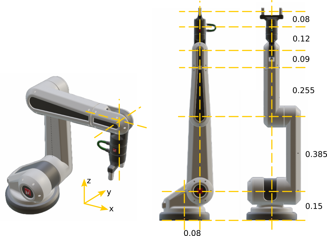
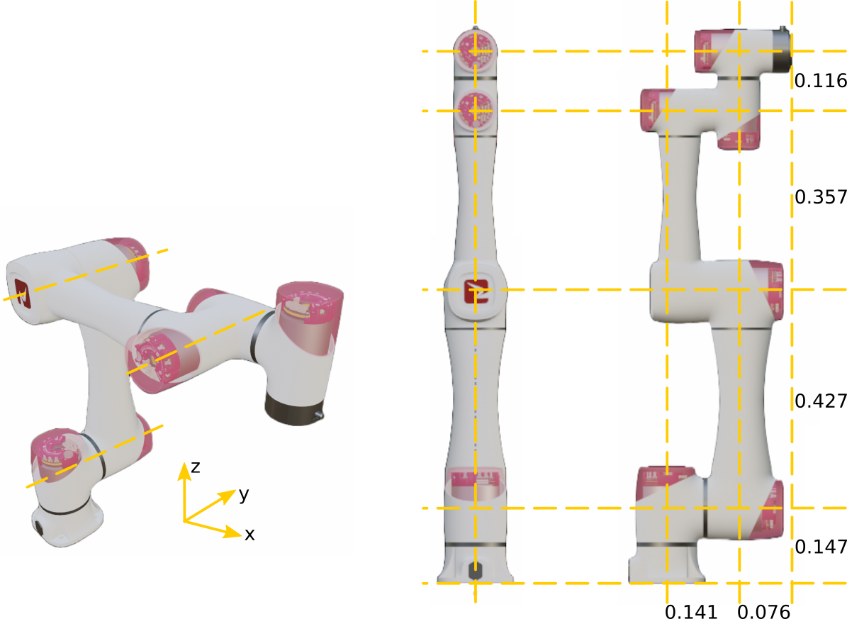
A parallel mechanism, such as a delta robot, uses a .json file and the parallel solver. See the mech-parameters.xml reference.
Describe the segments
Picture the robot with all joint angles at 0. For anthropomorphic2 that is the arm stretched straight up. Each segment is one step up the arm, from its own joint to the next one:
Each <segment number="N"> has two parts:
<tippose>›<position>: where the next joint sits, in m, measured from this segment’s joint. For the last segment, that is the flange.<jointaxis>: the axis this segment’s joint turns around or slides along:rot_x,rot_y,rot_z,tran_x,tran_yortran_z. Any other text,trans_xfor example, silently makes a fixed joint.
An analytical solver reads only some position values of each segment:
| Segment | anthropomorphic |
anthropomorphic2 |
planar |
|---|---|---|---|
| 1 | x, y, z | z | x |
| 2 | x, z | z | x |
| 3 | x, z | z | x |
| 4 | z | y | z |
| 5 | z | z | |
| 6 | z | y |
Warning
Set every value the solver does not read to 0, and leave segment orientations at 0. The forward kinematics use all values, so anything extra makes them disagree with the solver, and the robot jumps when you switch to Cartesian motion.
Example: from DH parameters
Robot data sheets usually give the geometry as DH parameters. This cobot fits anthropomorphic2:
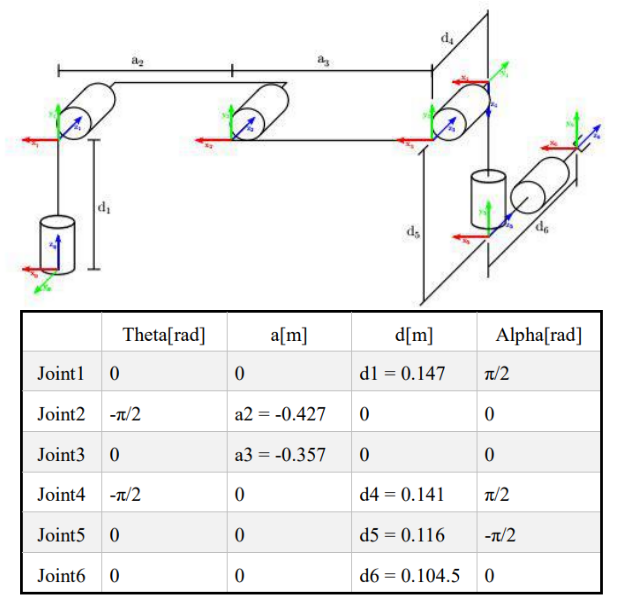
Each length becomes the one tip-pose value that anthropomorphic2 reads. The DH signs of a2 and a3 do not carry over: in the zero pose the arm points up, so those lengths are positive z.
| DH | Length | Segment | Tip pose |
|---|---|---|---|
d1 |
0.147 m | 1 | z = 0.147 |
a2 |
0.427 m | 2 | z = 0.427 |
a3 |
0.357 m | 3 | z = 0.357 |
d4 |
0.141 m | 4 | y = 0.141 |
d5 |
0.116 m | 5 | z = 0.116 |
d6 |
0.1045 m | 6 | y = 0.1045 |
The resulting mech-parameters.xml
<?xml version="1.0"?>
<robot name="Cobot" numberDoFs="6" ik_type="anthropomorphic2">
    <segment number="1">
        <tippose><position x="0.0" y="0.0" z="0.147"/></tippose>
        <jointaxis>rot_z</jointaxis>
    </segment>
    <segment number="2">
        <tippose><position x="0.0" y="0.0" z="0.427"/></tippose>
        <jointaxis>rot_y</jointaxis>
    </segment>
    <segment number="3">
        <tippose><position x="0.0" y="0.0" z="0.357"/></tippose>
        <jointaxis>rot_y</jointaxis>
    </segment>
    <segment number="4">
        <tippose><position x="0.0" y="0.141" z="0.0"/></tippose>
        <jointaxis>rot_y</jointaxis>
    </segment>
    <segment number="5">
        <tippose><position x="0.0" y="0.0" z="0.116"/></tippose>
        <jointaxis>rot_z</jointaxis>
    </segment>
    <segment number="6">
        <tippose><position x="0.0" y="0.1045" z="0.0"/></tippose>
        <jointaxis>rot_y</jointaxis>
    </segment>
    <tool name="tool">
        <tippose><position x="0" y="0" z="0"/></tippose>
    </tool>
</robot>
Set the tool point
The <tool> element places the tool point, seen from the flange. Unlike a segment, its <orientation> is used too, as a, b and c in rad around Z, Y and X:
<tool name="gripper">
    <tippose>
        <position x="0" y="0" z="0.12"/>
        <orientation a="0" b="0" c="0"/>
    </tippose>
</tool>
The <basepose> and <tool-offset> elements of older files are ignored. Set where the robot stands, and an extra tool offset, as in Frames and tool offset.
Add mass and inertia
You can move the robot without this step, but the model’s torques under root/ManipulatorControl/idJointTorque/ depend on it, and three features use them:
With every mass at 0 there is no error: all model torques are simply 0, so there is no gravity compensation and a collision detector compares against zero.
Add these to each segment, and to the tool if it carries weight:
| Element | What it is | Unit |
|---|---|---|
<mass> |
The mass of the segment | kg |
<cog> › <position> |
The centre of gravity, measured from the segment’s tip pose | m |
<inertia> |
The inertia around the centre of gravity, along the segment’s axes. Only Ixx, Iyy, Izz, Ixy, Ixz and Iyz are used |
kg·m² |
- Count each part once. The output shaft of a gearbox belongs to the segment it drives; the rest of the gearbox and the motor belong to the segment before it.
- Use the Motorcortex frame. Data sheets and CAD often give these values in their own frame. Turn them into x forward, y left, z up, with the robot in its zero pose.
Example: mass data of the six-axis cobot, before and after conversion
From the data sheet:
| Segment | Mass (kg) | Centre of gravity (m): x, y, z | Inertia (kg·m²): Ixx, Iyy, Izz |
|---|---|---|---|
| 1 | 5.096092 | -0.00004, -0.01290, -0.01726 | 0.0127270, 0.0096427, 0.0119825 |
| 2 | 10.70249 | -0.21335, 0.00000, 0.13058 | 0.0215573, 0.4351312, 0.4335571 |
| 3 | 4.341977 | -0.20021, 0.00000, 0.03962 | 0.0074610, 0.1187431, 0.1173773 |
| 4 | 1.835048 | -0.00019, -0.01377, -0.00809 | 0.0030334, 0.0021003, 0.0024817 |
| 5 | 1.877054 | 0.00014, 0.01278, -0.00773 | 0.0034297, 0.0021536, 0.0028632 |
| 6 | 0.449071 | 0.00000, -0.00009, -0.03035 | 0.0003376, 0.0003316, 0.0003881 |
In the Motorcortex frame:
| Segment | Mass (kg) | Centre of gravity (m): x, y, z | Inertia (kg·m²): Ixx, Iyy, Izz |
|---|---|---|---|
| 1 | 5.096092 | 0.00004, 0.01290, -0.01726 | 0.0127270, 0.0096427, 0.0119825 |
| 2 | 10.70249 | 0.00000, 0.13058, -0.21335 | 0.0215573, 0.4335571, 0.4351312 |
| 3 | 4.341977 | 0.00000, 0.03962, -0.20021 | 0.0074610, 0.1173773, 0.1187431 |
| 4 | 1.835048 | 0.00019, -0.01377, -0.00809 | 0.0030334, 0.0024817, 0.0021003 |
| 5 | 1.877054 | -0.00014, 0.01278, 0.00773 | 0.0034297, 0.0021536, 0.0028632 |
| 6 | 0.449071 | 0.00000, -0.03035, -0.00009 | 0.0003376, 0.0003881, 0.0003316 |
Segment 1 in the file:
<segment number="1">
    <tippose><position x="0.0" y="0.0" z="0.147"/></tippose>
    <jointaxis>rot_z</jointaxis>
    <mass>5.096092</mass>
    <cog><position x="0.00004" y="0.01290" z="-0.01726"/></cog>
    <inertia>
        <Ixx>0.0127270</Ixx> <Ixy>0</Ixy> <Ixz>0</Ixz>
        <Iyx>0</Iyx> <Iyy>0.0096427</Iyy> <Iyz>0</Iyz>
        <Izx>0</Izx> <Izy>0</Izy> <Izz>0.0119825</Izz>
    </inertia>
</segment>
Apply your changes
The file is not the only place these values live. control.xml can hold them too, and it wins:
Every save of the parameter tree, including Save Settings in the robot GUI, writes the segment and tool values into control.xml. From then on, a change in mech-parameters.xml has no effect until you remove those lines again. So how you apply a change depends on what you changed:
| What you changed | Where to change it |
|---|---|
| Tip poses, masses, centres of gravity, inertias | Live, in Motorcortex Desk |
| The solver, the number of axes, a joint axis | In the file, then clean up control.xml |
Change values live
Each segment is under root/ManipulatorControl/mechanism/segmentN/, the tool under mechanism/tool/:
| Parameter | Values |
|---|---|
tippose |
[x, y, z, rz, ry, rx], in m and rad |
mass |
kg |
cog |
[x, y, z], in m |
inertia |
[Ixx, Ixy, Ixz, Iyx, Iyy, Iyz, Izx, Izy, Izz], in kg·m² |
The model is rebuilt as soon as you write a value. Save the parameter tree to keep it; the values then go into control.xml. Copy them into mech-parameters.xml too, so the file stays a correct description of the robot.
Change the solver, axes or joint axes
These are read only from the file:
- Edit
mech-parameters.xml. - Open
control.xmland delete every line whose path starts withroot/ManipulatorControl/mechanism/segmentorroot/ManipulatorControl/mechanism/tool. Keep themechanism/frames/lines: the base and tool offset are not in the file.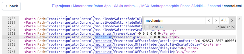
- Deploy the configuration.
- Check
root/ManipulatorControl/mechanism/info/:ikTypeandnumJointsmust match the file, and thesegmentN/tipposevalues must match your segments.
Check the model
- In simulation mode, jog the robot in joint mode to a few poses, and compare
root/ManipulatorControl/manipulatorToolPoseActualwith the pose you expect. - Jog in Cartesian mode: the tool must move along the axis you jog, without jumps.
- On the real robot, measure the tool point in a few poses and compare again.