Motorcortex Application Template
7 minute read
This section will explain how to create a new project and how the Motorcortex project template works.
CLion has a template available to create a new C++ Motorcortex project. How to install it check setting up development environment.
Installing Motorcortex Template Plugin
Creating a new C++ Motorcortex Project
-
In the
CLion Main MenuselectFile → New → Project → C++ Motorcortex. Then enter a newLocationfor your project and a project name. If your project requires aLogic Task, check the box to generate a logic template.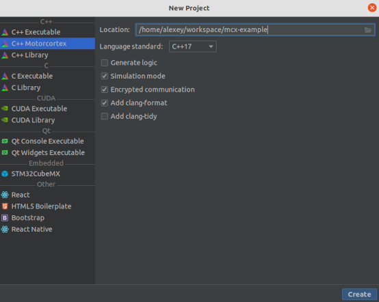
-
The generated template provides the following structure:
- The
configfolder contains all the necessary configuration for the application. - The
controlfolder contains basic implementation of the control blocks. - The
logicfolder contains basic implementation of the finite state machine. Main.cppcontains all the necessary code to start the application in real-time mode, according to the configuration from theconfig/config.json.
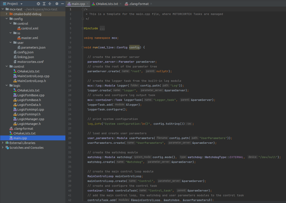
- The
To compile, run, debug and install the application, check the following section.
Configuration of the Motorcortex Application
Motorcortex applications follow the following structure for their configuration:
├── motorcortex.conf           # executable command line
├── config.json                # application startup parameters
├── linking.json               # defines links between parameters
├── license.pem                # license file
├── control
│   ├── control.xml            # application parameter values
│   └── persistence.bin        # persistent parameter values
├── io
│   └── master.xml             # Bus (EtherCAT)  configuration
└── user
    └── parameters.json        # user parameter definitions
In the following sections the configuration files are described in more detail. The example files are taken from the motorcortex application generator plugin for CLion (see developing-control-applications).
linking.json
In linking.json links between different parameters can be defined. This way you can communicate date from one Module to another Module. This works also across Tasks.
You should of course only link parameters that have the same type and size on both ends of the link. Also you cannot link something to an output (as Destination); an output can only be a Source.
The json schema that contsains all possible options you can download here: linking.schema.json.
{
  "Version": "1.0.0",
  "Groups": [
    {
      "Name": "LinkExample",
      "SystemMode": "All",
      "Links": [
        {
          "Source": {
            "Path": "root/Control/boolOutput"
          },
          "Destination": {
            "Path": "root/Logic/boolInput"
          }
        }
      ]
    },
    {
      "Name": "Simulation",
      "SystemMode": "Simulation",
      "Links": [
        {
          "Source": {
            "Path": "root/Simulator/doubleOutput"
          },
          "Destination": {
            "Path": "root/Control/doubleInput"
          }
        }
      ]
    }
  ]
}
license.pem
Although motorcortex components run about 30 minutes without a license (for testing purposes), to use motorcortex components in production you require a license. After you have purchased a license for your application components you will receive a license file that needs to be installed in the configuration folder. Make sure that the license file is named correctly according to the License setting in your config.json file.
control.xml and persistance.bin
In the control folder there are in general two files: control.xml and persistence.bin. control.xml contains control parameters which can be adjusted by the user. persistance.bin contains the values of parameters that are defined to be of type PARAMETER_PERSISTENT in your application. These parameters are continually saved during system operations, for instance a parameter that counts running hours of a system, that continues counting also after the system has been switched off; or if a system has relative encoders, their absolute values are continually saved, such that after a restart calibration is not required.
io/master.xml
master.xml contains the EtherCAT bus configuration. This file is created by using Motorcortex-ECAT.
user/parameters.json
In parameters.json parameters can be added to a motorcortex application without recompiling the application. This is useful when external processes or devices need to write data into a motorcortex application. For instance a vision system can use the Motorcortex API to write coordinates of an object into the UserParameters. THe robot application can then use these coordinates in a robot program.
Below is an example of a parameters.json file:
{
    "Version": "1.0",
    "Children": [
        {
            "Name": "IO",
            "Children": [
                {
                    "Name": "Gripper1",
                    "Type": "int32[1],parameter_volatile",
                    "Value": 0
                },
                {
                    "Name": "Gripper2",
                    "Type": "int32[1],parameter_volatile",
                    "Value": 1
                }
            ]
        },
        {
            "Name": "Branch2",
            "Children": [
                {
                    "Name": "branch2Param1",
                    "Type": "int32[3],input",
                    "Value": [2,3,4,5,6]
                },
                {
                    "Name": "branch2Param2",
                    "Type": "int32[3],input"
                },
                {
                    "Name": "subbranch1",
                    "Children": [
                        {
                            "Name": "branch2subbranch1Param1",
                            "Type": "char[11],parameter_volatile",
                            "Value": "Hello world"
                        },
                        {
                            "Name": "branch2subbranch1Param2",
                            "Type": "int,parameter_volatile",
                            "Value": 123
                        }
                    ]
                }
            ]
        },
        {
            "Name": "moduleParam1",
            "Type": "double[6],input",
            "Value": [
                1.34,
                2.23,
                3.5675,
                4.0034,
                5.5677,
                6.2345
            ]
        },
        {
            "Name": "moduleParam2",
            "Type": "bool,input"
        }
    ]
}
Programming Concepts
Modules and Tasks
A Motorcortex application is built around the concept of Modules and Tasks. A Module is an object that performs calculations based on inputs and internal variables and produces the outputs. The inputs are either set directly from a higher level Module (via the setter functions) or are set via the Parameter Tree. A Task provides an event loop to iterate the Modules. Task could contain multiple modules and iterate them sequentially with the required update rate. The Task could be configured to run with the real-time or with the normal priority.
Parameter Tree
In a Motorcortex application all the data is organized in a tree like structure, which is called a Parameter Tree. The Parameter Tree is used to communicate data inside and outside the application in a thread-safe manner. In the tree the control modules are represented as the nodes (folders) and control blocks' data is represented as leafs (parameters).
The Parameter Tree contains a snapshot of all the registered inputs, outputs and internal data of the modules at the current time. Modules can be nested and register their own parameters in the tree.
The Parameter Tree always starts from the root node, which is passed to the modules and tasks that then can register their own parameters or create submodules that register their own data.
Structure of the Module
All Motorcortex modules have a certain structure, which describes the life-cycle of the module. Modules go through different phases of the life-cycle during startup according to the schematic below.
   ┌──────────────────────────────┐
   │   Not Initialized            │
   └───┬──────────────────────────┘               ┌─────────────────────────────────────┐
       │ (Event: create)                          │ Creates modules and submodules.     │
   ┌───v───────┐                                  └───┬─────────────────────────────────┘
   │   Phase0  │                                      │ (Event: configure)
   └───┬───────┘                                  ┌───v─────────────────────────────────┐
       │ (Event: initPhase1)                      │ Add parameters to the tree          │
       │                                          │                                     │
   ┌───v───────┐                                  └───┬─────────────────────────────────┘
   │   Phase1  │                                      │ (Event: start)
   └───┬───────┘                                  ┌───v─────────────────────────────────┐
       │ (Event: initPhase2)                      │ Parameter tree is ready,            │
       │                                          │                                     │
   ┌───v──────────────────────────┐               └───┬─────────────────────────────────┘
   │   Phase2                     │                   │
   └───┬──────────────────────^───┘               ┌───v─────────────────────────────────┐
       │ (Event: startOp)     │ (Event: stopOp)   │  Real-time event loop is            │
       │                      │                   │  ready to start.                    │
   ┌───v──────────────────────┴───┐               └─────────────────────────────────────┘
   │   Operation                  │
   └───┬──────────────────────────┘
       │ (Event: exit)
   ┌───v───────┐
   │ Destroyed │
   └───────────┘
Modules are first created by calling the Modules’ create_ function. This in turn calls the create method of all sub-modules to register all the Modules in the Parameter Tree.
Then the Modules are added to a Task and the Task’s configure method is called. This calls initPhase1_ of all the (sub-)modules. In initPhase1_ all (sub-)modules shall add their Parameters to the Parameter Tree.
// hpp file
class MainControlLoop : public mcx::container::Module {
public:
  MainControlLoop() = default;
  ~MainControlLoop() override = default;

private:
  void create_(const char* name, mcx::parameter_server::Parameter* parameterServer, uint64_t dtMicroS) override;
  bool initPhase1_() override;
  bool initPhase2_() override;
  bool startOp_() override;
  bool stopOp_() override;
  bool iterateOp_(const mcx::container::TaskTime& systemTime, mcx::container::UserTime* userTime) override;

  double input_{};
  double output_{};
  double gain_{1.0};

  LowPassFilter lowPassFilter_;
};
// cpp file
using namespace mcx;

void MainControlLoop::create_(const char* name, parameter_server::Parameter* parameterServer, uint64_t dtMicroS) {
   createSubmodule(&lowPassFilter_, "LowPassFilter");
}

bool MainControlLoop::initPhase1_() {
  using namespace mcx::parameter_server;
  addParameter("input", ParameterType::INPUT, &input_);
  addParameter("output", ParameterType::OUTPUT, &output_);
  addParameter("gain", ParameterType::PARAMETER, &gain_);
  return true;
}

bool MainControlLoop::initPhase2_() { return true; }

bool MainControlLoop::startOp_() { return true; }

bool MainControlLoop::stopOp_() { return true; }

bool MainControlLoop::iterateOp_(const container::TaskTime& systemTime, container::UserTime* userTime) {
  output_ = gain_ * input_;
  lowPassFilter_.setInput(output_);
  lowPassFilter_.iterate(systemTime, userTime);
  return true;
}
Now that the Parameter Tree is complete and running Phase1, Parameter values can be loaded from a file.
Then Task can be started by calling its startOp_ method. This calls the initPhase2_ methods of all (sub-)modules and then startOp_, just before the task switches to the realtime mode.
In the operation state, the system cyclically calls the Module’s iterateOp_ method that calculates the new state in each timestep. In the iterateOp_ method all submodules also need to be iterated.