Manipulability - How to change the manipulability of your robot.
Inputs
The standard robot application has a position or speed input, by default set to speed input. There is made distinction between:
Joint Input - The movement of each axis individually to get desired end-effector motion.
Tool Input - The movement of axes combined to get a desired end-effector motion.
Joint Input
The UI provides a set of jogging joystick, which are visible after selecting Manual Joint. Joint input selection take place in: DESK-tool in tree path: root/Control/gotoJogMode set to 1 = Joint Velocity Input or to 0 = Joint Trajectory Input.
Joint Velocity
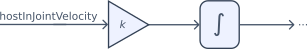
Per default the joystick vertical path is linked to root/Control/hostInJointVelocity. Inside nudge vertical and range vertical you define the maximum velocity [rad/s]. Check out joystick explained for more information.
Joint Velocity Gain
With DESK-tool in tree path: root/Control/hostInJointVelocityGain you find the Joint Velocity Gain parameter, this value is multiplied with the ../hostInJointVelocity. The ../hostInJointVelocityGain is a scaling factor toward the integrator and be used to quickly change the joint velocity.
Inside the path: root/Control/jointJogIntegrator/.. you can activate and parameterize the input and output.
Parameter path:
Description:
../inputLimiterOn
Set to 1 to activate velocity input limiter.
../inputLimiterMin
Define the minimum input velocity [rad/s] towards the integrator.
../inputLimiterMax
Define the maximum input velocity [ras/s] towards the integrator.
../outputLimiterOn
Set to 1 to activate position output limiter.
../outputLimiterMin
Define the minimum output position [rad].
../outputLimiterMax
Define the maximum output position [rad].
Joint Trajectory
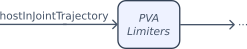
To control the robot joints via trajectory input, you have to set joystick vertical path to root/Control/hostInJointTrajectory. Inside nudge vertical and range vertical you define the maximum trajectory [rad]. Check out joystick explained for more information.
Warning
If you apply a step response to the hostInJointTrajectory, the risk of position jump is high, so be careful when performing this kind off.
Joint Trajectory Limiter
Inside the path: root/Control/jointTrajectoryLimiters/pvaLimiter0X/.. you can activate and parameterize the input and output.
Parameter path:
Description:
../pvaInputsOn
Set to 1 to activate position input limiter.
../upperLimit
Define the minimum position [rad].
../lowerLimit
Define the maximum position [rad].
../maxVelocity
Define the maximum velocity [rad/s].
../maxAcceleration
Define the maximum acceleration [rad/s/s].
../w
Is input filter, set to maximum value because this value is self adjusting.
Tool Input
The GUI provides a set of translation and rotation joysticks, which are visible after selecting Manual Cartesian.Tool input selection take place in: DESK-tool in tree path: root/Control/gotoJogMode set to 1 = Tool Velocity Input or to 0 = Tool Trajectory Input.
Tool Velocity
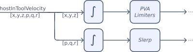
Per default the joystick vertical/horizontal path are linked to root/Control/hostInToolVelocity. Inside nudge vertical, nudge horizontal, range vertical and range horizontal you define the maximum velocity for translation [m/s] and rotation [rad/s]. Check out joystick explained for more information.
Tool Trajectory
To control the robot in cartesian space, via trajectory input, you have to set the joystick vertical/horizontal path to root/Control/hostInToolTrajectory. Inside nudge vertical, nudge horizontal, range vertical and range horizontal you define the maximum velocity for translation [m] and rotation [rad]. Check out joystick explained for more information.
Signal Generators
Two types of signal generators are integrated to the robot application:
and jlpJerkFactor path (../signalGenerator0X/jlpJerkFactor)
can be changed in order to change the signal profile.
Joint Reference Generator
The Joint Reference Generator is a signal generator which is added to the joint inputs. This signal generator, which is disabled per default can be enabled and parameterized inside the path: root/Control/jointReferenceGenerator/signalGenerator0X.
Cartesian Translation Reference Generator
The Cartesian Trans Reference Generator is a signal generator which is added to the tool input. This signal generator, which is disabled per default can be adjusted inside the path: root/Control/cartTransReferenceGenerator/signalGenerator0X.
Window Detectors
Window detectors are used to trigger a warning or an e-stop. Each window detector contains the following set of inputs:
Alarm
Description
enable
To enable the detector set the value to 1 or disable the detector set value to 0.
Too Low
If the input signal is less than the too low value an Emergency Stop Error is triggered.
Low
If the input signal is less than the low value a Warning is triggered.
High
If the input signal is higher than the high value a Warning is triggered.
Too High
If the input signal is higher than the too high value an Emergency Stop Error is triggered.
Position Window Detector
The position Window monitors the absolute position in [rad] per axis. Inside the GUI under window detector tab you can set the Position Window Detectors parameters or via the tree under the path: root/Control/actuatorControlLoops/actuatorControlLoop0X/positionWindowDetector.
Velocity Window Detector
The velocity Window monitors the velocity in [rad/s] per axis. Inside the GUI under the window detector tab you can set the Velocity Window Detectors parameters or via the tree under the path: root/Control/actuatorControlLoops/actuatorControlLoop0X/velocityWindowDetector.
Acceleration Window Detector
The Acceleration Window monitors the acceleration in [rad/s/s] per axis. Inside the GUI under the window detector tab you can set the Acceleration Window Detectors parameters or via the tree under the path: root/Control/actuatorControlLoops/actuatorControlLoop0X/accelerationWindowDetector.
Torque Window Detector
The Torque Window monitors the torque in [N.m] per axis. Inside the GUI under the window detector tab you can set the Torque Window Detectors parameters or via the tree under the path: root/Control/actuatorControlLoops/actuatorControlLoop0X/torqueWindowDetector.
Position Error Window Detector
The Position Error Window monitors the position error (difference between commanded position and actual position) in [rad] per axis. Inside the GUI under the window detector tab you can set the Position Error Window parameters or via the tree under the path: root/Control/actuatorControlLoops/actuatorControlLoop0X/positionErrorWindowDetector.
Joint Setpoint Jump Detectors
The Joint Setpoint Jump Detector monitors if a setpoint jump occurs (difference between current setpoint and previous setpoint) in [rad] per axis. Inside the GUI under the window detector tab you can set the Joint Setpoint Jump Detector parameters or via the tree under the path: root/Control/jointSetpointJumpDetectors/windowDetector0X.
X Window Detector
The X Window monitors the position in x direction in [m] you can set the x window detector via the tree under the path: root/Control/xWindowDetector.
Y Window Detector
The Y Window monitors the position in y direction in [m] you can set the y window detector via the tree under the path: root/Control/yWindowDetector.
Z Window Detector
The Z Window monitors the position in z direction in [m] you can set the z window detector via the tree under the path: root/Control/zWindowDetector.
Actual Manipulability Detector
The Actual Manipulability Detector monitors the actual manipulability you can set the actual manipulability detector via the DESK-tool under the path: root/Control/actualManipulabilityDetector.
RT Violation Window Detector
The RT Violation Window monitors the realtime of the system in [ms] set the RT violation detector via DESK-tool under the path: root/Control/rtViolationWindowDetector.
Actuator Limiters
The actuator limiters allow you to set the position, speed and acceleration limits of each axis. Adjustments take place in: DESK-tool in tree path: root/Control/actuatorLimiters/pvaLimiter0X/.. or in GUI Axis Settings Tab.
Parameter path:
Description:
../enable
Set to 1 to activate PVA-limiters.
../lowerLimit
Set this value to the lower position limit in [rad].
../upperLimit
Set this value to the upper position limit in [rad].
../maxVelocity
Set this value to the max allowable axis velocity in [rad/s] defined by the manufacturer.
../maxAcceleration
Set this value to the maxVelocity*10 in [rad/s/s], rule of thumb to prevent setpoint overshoot while decelerating motion is to low.
Manipulability
The Manipulability indicates how moveable the robot is. If the robot is in a singular point, the manipulability will be 0. Switching to manual Cartesian in a singular point could lead to position jumps. To avoid this you can enable and adjust the Actual Manipulability Detector such that you are never able to start your robot in manual cartesian mode if the robot is located in a singular point.
Actual Manipulability
The actual manipulability is visible inside the path:root/Control/actualManipulability. If the number is 0 the robot pose is in its singular position. To understand the relation between robot pose and manipulability, you should switch the robot to manual joint mode and open the actualManipulability. Move each joint separately, in order to figure out which joints have influence on the manipulability of your robot. Try to understand how the robot behaves and adjust the Actual Manipulability Gain Lookup table such, that you have a smooth transition.
Warning
Changing Manipulability Gains can lead to potential robot jumping, always adjust the parameters in simulation mode! When tested in Simulation mode and the robot does not jump, you can switch to production mode.
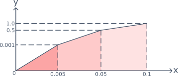
Manipulability Gain Lookup
The actual manipulabilityGain defines, the gain applied to the movement, if the gain = 0 the rate of movement = 0.
With the manipulabilityGainLookup you can define the rate of deceleration towards a singular pose.
Parameter
Description
input
The input is linked to the actualManipulability.
numPoints
The numPoints indicate how many table values are used.
output
Indicates the manipulabilityGain as result of the lookup table.
x
In the x table, you define the actual manipulability for each range xn, x(n+1), …
y
In the y table you define the manipulabilityGain based on the actual manipulability range yn, y(n+1), …