Generic Control Case
7 minute read
Introduction
This document is the User Manual for the Generic Control Cabinet.
The Vectioneer Generic Control Case (GCC) is a complete Industrial Motion Control and Safety System in a small form-factor. It has everything you need to control any EtherCAT-based Machine or Robot safely. Out-of-the-box it is set-up with the Motorcortex-Generic-App pre-installed. This allows you to control multiple EtherCAT servo axis and numerous EtherCAT IO straight from a connected web-browser. No software installation required.
System Overview
The Generic Control Case allows easy control of EtherCAT slaves. It also provides (limited) onboard power to supply externally connected EtherCAT devices. Two EtherCAT branches can be connected to the two EtherCAT sockets on the front panel.
An integrated FSoE (FailSafe over EtherCAT) master provides a complete safety system, that can be extended with extra FSoE slaves if needed. As a standard one two-channel Emergency Stop input and a 2 channel STO output are provided and configured.
The (typical) System Overview is shown in the figure below.

Optionally the Generic Control Case can be extended with an Application Case that will provide a robot or machine with power or servo amplifiers. Vectioneer has a standard Application 48v case for 48VDC robots.
what’s in the box
After Buying a GCC you the following components should be in the box:
- 1x Generic Control Cabinet
- 1x IEC C13 Power cable with Schuko (EU) plug
- 1x Ethernet cable (1m)
- 1x E-stop Button
- 1x E-Stop Cable (5m)
- 2x Spare Male M12 A-coded Connectors
- 1x Spare Female M12 A-coded Connector
Connecting the Generic Control Case
To connect the Generic Control Case to your pc you will need to go trough te following steps.
- Connect the powercable to the power connector and a powerinlet
- Connect the E-stop using the E-stop Cable at the E-stop M12 connector.
- Connect the Yellow Ethernet Cable to the ENET port and your PC.
- Turn on your Generic Control case by pressing the Power Switch.
- The status light should light up white.
To continue setting up the connection to your Generic Control Case follow the steps at Getting Started.
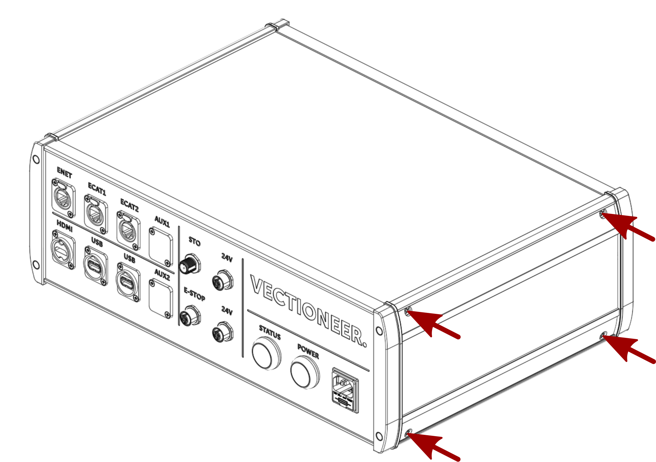
Generic Control Case Connections
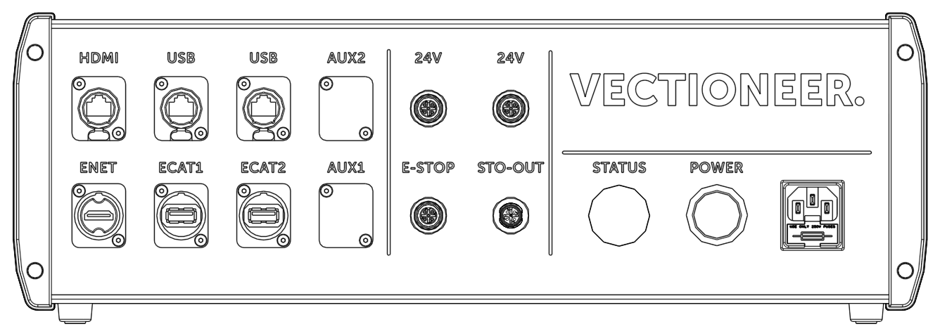
This chapter will provide more information on how to connect the hardware of the Generic Control Case. All of the connectors are located on the front panel of the Case. The figure below provides an overview of all connectors, which can be grouped as:
- Power Connector
- Supply Voltage Connectors
- Safety Connectors
- Networking Connectors
- Media Connectors
Power In Connector
The Generic Control Case Receives power trough the Fused IEC C14 Power inlet. Voltage supplied should be between 85 and 264VAC.
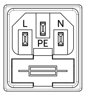
Note
Always make sure the correct fuse is placed in the fuse holder. Standard a 5x20mm 3.5A speed T fuse is placed inside the fuse holder.
24VDC Out Connectors
The 24V DC supply voltage connectors at the front of the case are two Female A-coded M12 connectors marked with 24V. These connectors provide a interface for Us “bus voltage” +24V DC and Up “auxiliary voltage” power to the user. The figure below shows the pin-out of these connectors.

| Pin | Description |
|---|---|
| 1 | +24 V DC Us (Σ 2A max for all Us) |
| 2 | +24 V DC Up (Σ 3 A max for all Up) |
| 3 | 0 V DC |
| 4 | 0 V DC |
| 5 | PE |
The 24V DC output is protected from over current and over voltage protection values can be found in the table below.
| Case Internal Protection | |
| Over-current protection | 3A Circuit Braker |
| Over-voltage Protection | 27.60 to 33.60V Automatically resetting |
| Logic Out Protection (Us) | |
| Over-current protection | 2A Circuit Braker |
| Over-voltage Protection | 27.60 to 33.60V Automatically resetting |
| Auxiliary Power Protection (Up) | |
| Over-current protection | 4.2A Circuit Braker |
| Over-voltage Protection | 27.60 to 33.60V Automatically resetting |
Note
The over-voltage protection of the Internal Case and Logic Out is combined.
Note
Note that the circuit brakers can be manually reset by the user.
Safety connectors
The GCC has two safety connectors, that can be easily identified by their yellow insert. These connectors allow the user to easily hook-up safety devices.
- An Emergency Stop button can be connected to the female A-coded M12 connector.
- A Safe output is available on the male A-coded M12 connector and can be used for e.g.for STO “Safe Torque Off” on Motor drives or a Safety Relay.
The figure below shows the pin-out of these connectors.
Emergency Stop
The GCC is outfitted with a M12 yellow e-stop connector for connecting the E-stop that comes in the box.

| Pin | Description |
|---|---|
| 1 | Pulse Output 1 |
| 2 | Safe Input 1 |
| 3 | Pulse Output 2 |
| 4 | Safe Input 2 |
| 5 | N.C. |
STO-out
The STO-OUT Connector on the GCC is desitined for components using a safe torque off (STO) function. Using a Application Cabinet 48V the STO-OUT should be connected to STO-IN.

| Pin | Description |
|---|---|
| 1 | +24 V DC Us (Σ 2A max for all Us) |
| 2 | STO channel 1 (24v DC, 0.5A max) |
| 3 | 0 V DC |
| 4 | STO channel 2 (24v DC, 0.5A max) |
| 5 | Feedback STO (non-safe) |
The image below will provide an example of wiring STO output to drives with STO-input:
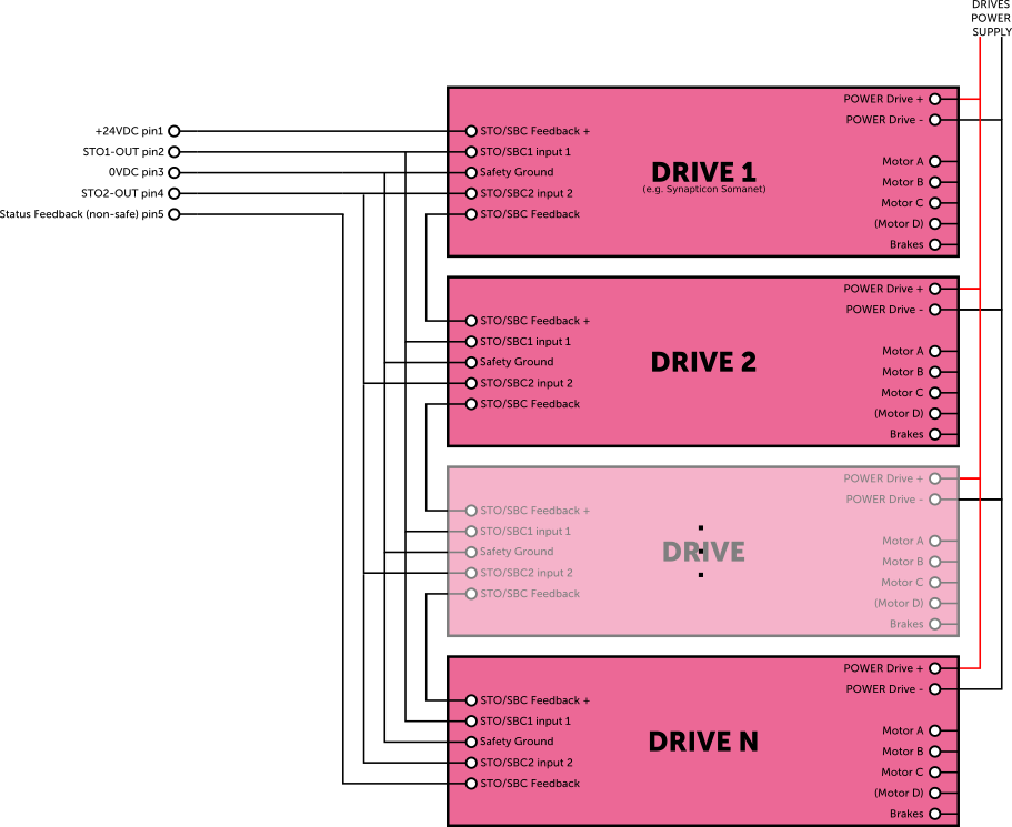
Example of STO-out connection to drives with STO-input
Alternatively, the STO can also be used with some types of Safety Relays if STO is not available on the drives. An example is given below:
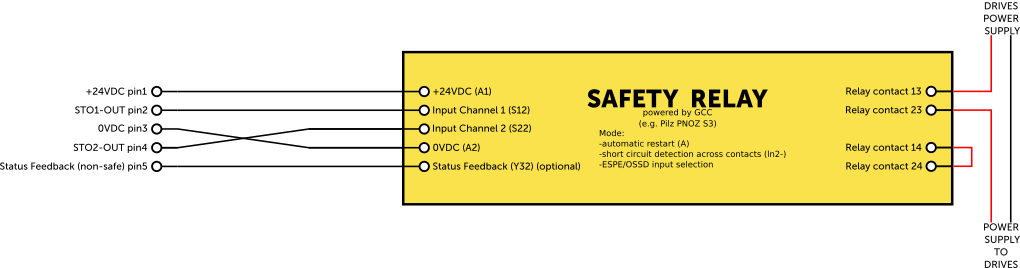
Warning
Make sure that the Safety Relay is dimensioned for the load of the drives and motors.
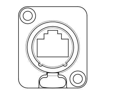
Networking Connectors
On the top left of the front panel there are three RJ45 Cat6E ports. The table below provides an overview of the network ports
| Port | Description |
|---|---|
| ENET | Gigabit Ethernet port (Used to connect to Motion PC), do not connect EtherCAT to this port |
| ECAT1 | EtherCAT (Used to connect EtherCAT device), do not connect Ethernet to this port |
| ECAT2 | EtherCAT (Used to connect EtherCAT device), do not connect Ethernet to this port |
Note
That the ECAT2 port is always the last EtherCAT chain in the bus.
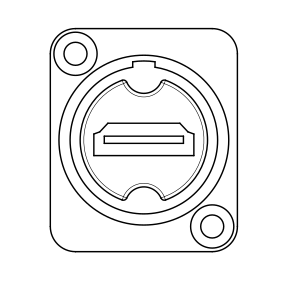
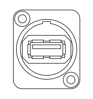
Media Connectors
On the bottom left of the front panel there are several media connectors. The table below provides detailed information:
| Port | Description |
|---|---|
| HDMI | 1.4 4K @ 30 Hz |
| USB | Blue: USB 3.0 White: USB 2.0 |
| USB | Blue: USB 3.0 White: USB 2.0 |
Auxiliary ports
On the front panel there are also two auxiliary ports marked with AUX. These ports are not connected and optional for the user to add extra port(s) via an connector that has an XLR form factor.
Operation of the Generic Control Case
This chapter provide more detail of operating the Generic Control Case. this chapter will go trough
- switching on
- switching off
- connecting to Generic control cabinet
Switching the Case on
The Generic Control Case can be turned on by pressing the latching power button. When pressed the button should light up White, indicating that the case is powered with 24V DC. If the case does not power up its possible that one of the circuit breakers has been tripped. Resetting the internal circuit breaker manually has to be done by the following steps:
Warning
Make sure that the power cable is removed from the case before opening the case.
- Remove the side cover by removing the rubber strips with 4 Phillips screws as shown in the figure below.
- Reset the circuit breaker by pressing the button on top of the circuit breaker. The Location of the circuit breaker is shown in the figure below.
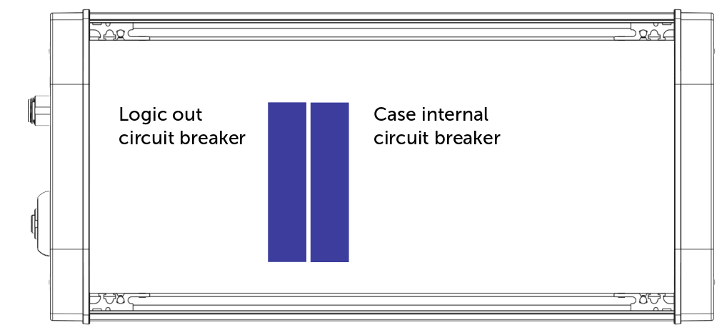
- When finished mount the right cover back on to the case. Make sure all that all panels line out correctly before fastening the Phillips screws.
If the case is powered the Motion PC will automatically start-up and the Status light will light up white if the system is “OK”
The Status Lamp is an RGB LED that is connected to 3 digital outputs (one for each channel). The Color of the lamp can be changed by changing the outputs accordingly from the Control Application. In the default installed Generic Application the Status Lamp pis configured as follows:
| Status lamp color | meaning |
|---|---|
| White | System Okay |
| Yellow | A Warning is active |
| Red | An Error is active (Forced Disengage or Emergency Stop) |
Note
More detail of these errors can be found in the GUI of the generic-app also it is possible to reset the errors in this GUI.
Switching the Case off
The Generic Control Case can be Turned Off by pressing the Power button such that it pops up to its off position. The power will be removed from the case.