Application Case 48V
4 minute read
Introduction
This document is the User Manual for the Vectioneer Application Case 48V and a addition to the Generic Contol Case. This case provides 48v and a Interface for more demanding applications for example Robots.

Application Case 48V connections
This chapter will explain how to connect the hardware of the Application Case 48V. All of the connectors are located on the front panel of the Case.
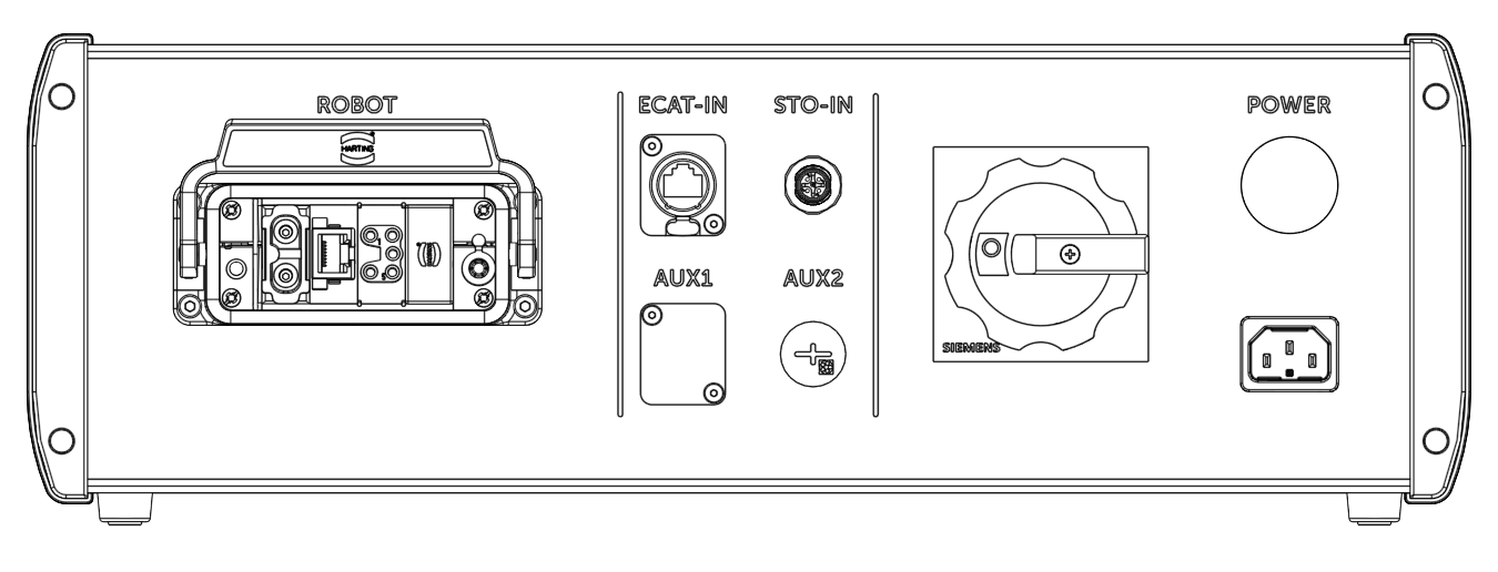
Power Connector
The Application Case 48V Receives power trough the IEC C14 Power inlet. Voltage supplied should be between 100 and 250VAC. Inside the Case there is a 10A Circuit breaker to protect the power Inlet.
Warning
The Circuit breaker is designed for protection on CE regulation. This will result in reduced power of the 48V power supply when using +/- 100V. It is possible to place a 15A Circuit breaker according to UL regulation.
STO IN connector
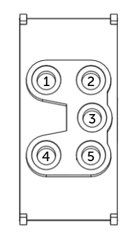
A Male A-coded M12 connector provides Safe output for STO (Safe Torque Off) from the Generic Control Case to the Robot Connector. The figure below shows the pin-out of this connector.
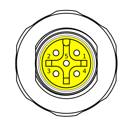
| Pin | Description |
|---|---|
| 1 | +24 V DC Us (Σ 2A max for all Us from GCC) |
| 2 | STO channel 1 (24v DC, 0.5A max) |
| 3 | 0 V DC |
| 4 | STO channel 2 (24v DC, 0.5A max) |
| 5 | Feedback STO (non-safe) |
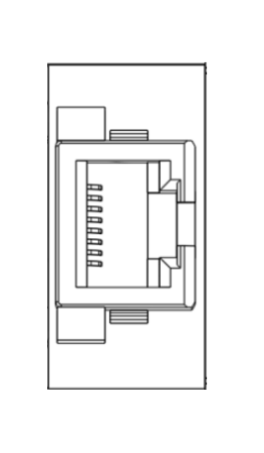
The image below will provide an example of wiring STO output to drives with STO-input:
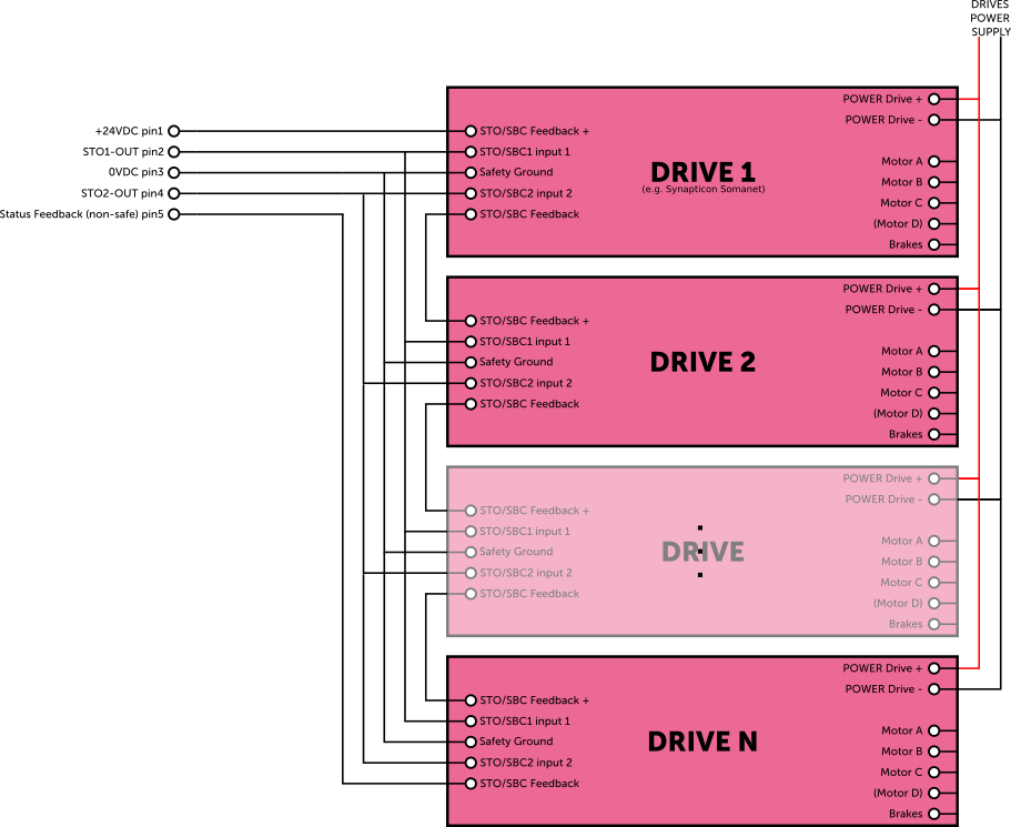
Altenatively, the STO can also be used with some types of Safety Relays if STO is not available on the drives. An example is given below:
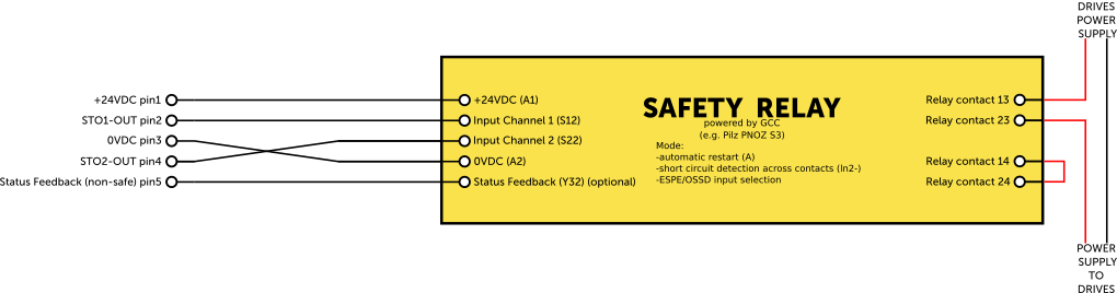
Note
Make sure that the Safety Relay is dimensioned for the load of the drives and motors.
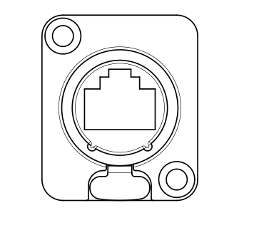
EtherCAT IN Connector
On the front panel there is one RJ45 Cat6E port. It is possible to use this port to connect a EtherCAT port from the Generic Control Case to the Robot Connector.
Auxiliary ports
On the front panel there are also two auxiliary ports marked with AUX. These ports are not connected and optional for the user to reconfigure.
Robot Connector
The Application Case 48V has one Robot Connector for the user to connect a robot to. And still make it possible to connect separately without connector. In the robot connector there are three connectors:
- 48V DC power connectors
- Robot EtherCAT Connector
- Robot STO Connector
48V DC power OUT Connector
On the Application Case 48V has an internal voltage of 48V DC. On the front Panel in the Robot connector position A there is a 2 Pole connector for the user. Protection values can be found in the table below:
| Case Protection | |
|---|---|
| Over-current protection | 32A Self resetting Circuit breaker |
| Over-voltage Protection | 57.00 to 67.20 Automatically resetting |
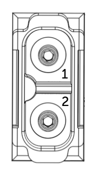
| Pin | Description |
|---|---|
| 1 | +48 V DC Us (32A max) |
| 2 | 0 v DC |
EtherCAT OUT Connector
In the Robot Connector Position B There is a RJ45 Interface to connect to EtherCAT.
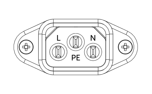
STO OUT connector
In the Robot Connector Position C there is a 5 pole connector for STO.
| Pin | Description |
|---|---|
| 1 | +24 V DC Us (2A max) |
| 2 | STO channel 1 (24v DC, 0.5A max) |
| 3 | 0 V DC |
| 4 | STO channel 2 (24v DC, 0.5A max) |
| 5 | PE |
Switching the Case on
The 48V Application Case can be turned on by rotating the main disconnector. When set to “1” the Status LED should light up White, indicating that the Case is provided with 48V DC.
If this it not the case it might be possible that the circuit breaker is tripped. Resetting the Circuit breaker can be done by the following steps
Warning
Make sure that the Power Cable is removed from the case before opening the case.
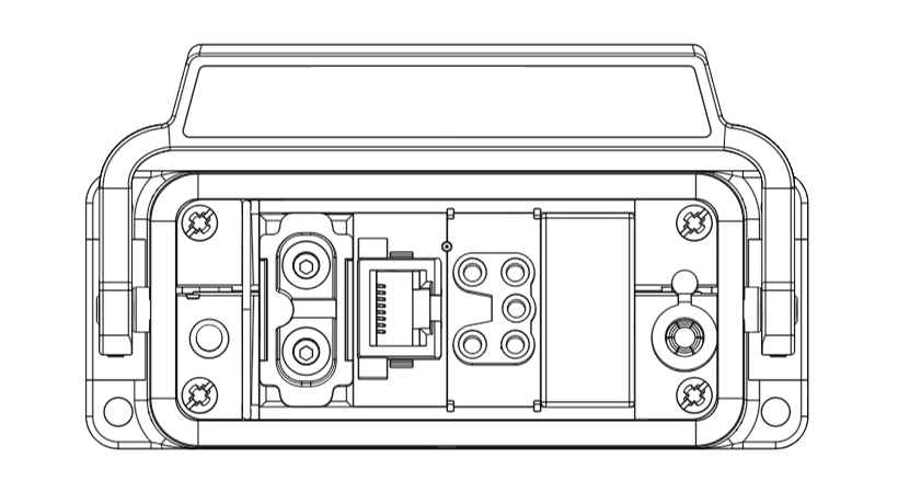
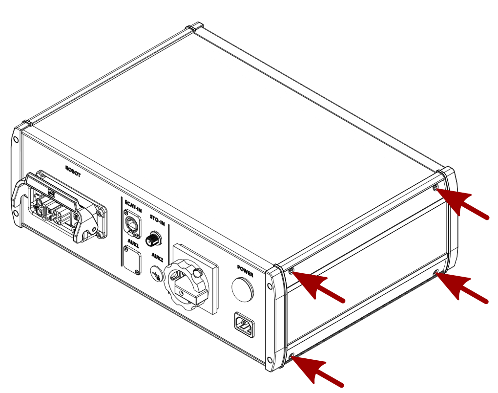
- Remove the side cover by removing 4 Phillips screws as shown in the figure below
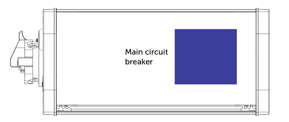
- Reset the circuit breaker by flicking the the switch on top of the circuit breaker. Location of the circuit breakers is shown in the figure below.
- When finished mount the right cover back on to the case. Make sure all that all panels line out correctly before fastening the Phillips screws.
Note
After any Fault the User shall check the cause of the Fault and make sure the problem is solved.
Switching the Case off
The 48V Application Case can be Turned Off by rotating the main disconnector. When set to “0” the Status LED will fade out, indicating that the Case is no longer provided with 48V DC.
Warning
Keep in mind that the Disconnector will turn off the 48 VDC. All other instances like STO and EtherCAT will stay connected.