Alarm devices
5 minute read
The alarm devices turn a number, normally the robot state, into on and off signals for a signal light or a beeper. There are two of them, Beeper and Light, and they work the same way. Out of the box they are linked to the robot state, but every output is 0: you choose what each state looks or sounds like.
How it works
Each device has five sequencers, Sequencer01 to Sequencer05, and three output channels. Every control cycle:
- The device writes
defaultOutputtooutput. - Each sequencer compares the input with its
ids. A sequencer with a match plays its sequence and writes it tooutput, instead ofdefaultOutput. - If more than one sequencer matches, the one with the highest number wins.
- A sequencer without a match stops and starts from the beginning the next time it matches.
Choose the input
In the standard configuration, the group From Logic To Alarm in linking/base.link.json links the robot state to both devices:
{
  "Name": "From Logic To Alarm",
  "SystemMode": "All",
  "Enable": true,
  "Links": [
    { "Source": { "Path": "root/Logic/state" }, "Destination": { "Path": "root/AlarmDevices/Beeper/input" } },
    { "Source": { "Path": "root/Logic/state" }, "Destination": { "Path": "root/AlarmDevices/Light/input" } }
  ]
}
These are the values of root/Logic/state you can use as ids:
| State | Value | Drives |
|---|---|---|
INIT_S |
0 |
Off, while the application starts |
OFF_S |
1 |
Off |
IDLE_S |
2 |
On |
ENGAGED_S |
4 |
On, the robot can move |
HOMING_S |
5 |
On, the robot is homing |
FORCEDIDLE_S |
6 |
On, stopped after an error |
ESTOP_OFF_S |
7 |
Off, after an emergency stop |
Transition values
Between two states, root/Logic/state briefly holds a transition value. They last only as long as the transition, so they are rarely useful as ids.
| Transition | Value |
|---|---|
OFF_TO_IDLE_T |
102 |
IDLE_TO_OFF_T |
201 |
IDLE_TO_ENGAGED_T |
204 |
PAUSED_TO_IDLE_T |
302 |
ENGAGED_TO_PAUSED_T |
403 |
TO_FORCEDIDLE_T |
600 |
RESET_FORCEDIDLE_T |
602 |
TO_ESTOP_T |
700 |
RESET_ESTOP_T |
701 |
To drive a device from something else, change the Source of its link, for example to one of your own user parameters. See link files.
Set a sequence
A sequence has five steps. Each step sets all three channels for a time, and the sequence then loops for as long as the input matches. The parameters are under root/AlarmDevices/Light/ or root/AlarmDevices/Beeper/:
| Parameter | What it does | Standard configuration |
|---|---|---|
defaultOutput |
The value of the three channels when no sequencer matches | 0 0 0 |
SequencerNN/ids |
Up to three input values that start this sequencer. -1 means not used |
-1 -1 -1 |
SequencerNN/durations |
How long each of the five steps lasts, in s | 0 0 0 0 0 |
SequencerNN/channel_01 to channel_03 |
The value of output[0] to output[2] in each of the five steps |
0 0 0 0 0 |
output |
Output: the three channels, to link to your lamps or beeper |
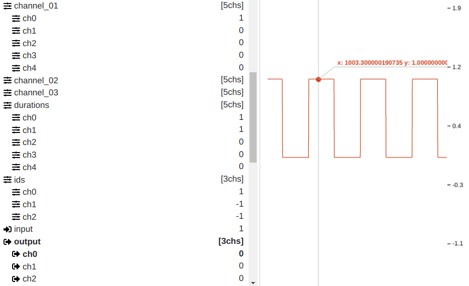
Which channel is which colour depends on how you wire the outputs. The example below blinks output[0], for example a red lamp, at 1 Hz:
A step with duration 0 still lasts one control cycle. For a pattern with fewer than five steps, give the extra steps duration 0 and the same values as the step before them, so they do not cause a short flash.
Example: a signal light
With output[0] wired to a red lamp and output[1] to a green lamp, these settings give steady green while the robot is engaged, and blinking red after an error or an emergency stop:
| Parameter | Value | Why |
|---|---|---|
Sequencer01/ids |
4 -1 -1 |
Engaged |
Sequencer01/channel_02 |
1 1 1 1 1 |
Green on in every step |
Sequencer01/durations |
1 1 1 1 1 |
Any value works for a steady light |
Sequencer02/ids |
6 7 -1 |
Forced idle or emergency stop |
Sequencer02/channel_01 |
1 0 0 0 0 |
Red on, then off |
Sequencer02/durations |
0.5 0.5 0 0 0 |
0.5 s on, 0.5 s off |
Set the values in Motorcortex Desk and save the parameter tree to keep them.
What this looks like in Motorcortex Desk
A sequencer that blinks output[0] while the input is 1: channel_01 is 1 0 0 0 0 and durations is 1 1 0 0 0.
Link the output
output is not linked to any hardware in the standard configuration. Link it to a digital output of an EtherCAT I/O module in the ECAT tool: open the module’s rxPDO tab, find the output channel and link it to root/AlarmDevices/Light/output. The channel number picks the element: channel 0 is output[0]. See Digital I/O for adding and linking an I/O module.
Check it
- Deploy the configuration and open Motorcortex Desk.
- Switch the robot between off, idle and engaged, and watch
root/AlarmDevices/Light/outputchange with the state. - On the real machine, check that each lamp and the beeper follow the output.
Next: Step 6: add a 3D model.