ActuatorControlLoop
ActuatorControlLoop is the control loop for a single axis.18 minute read
ActuatorControlLoop is the control loop for a single axis. It converts sensor
readings into engineering units, decides what the axis should be doing,
converts that back into drive units, and watches everything for faults.
Everything else in this library exists to feed or be fed by this block.
flowchart LR
    i1(["inputPosition, inputVelocity, inputAcceleration, inputTorque"]) --> B["ActuatorControlLoop"]
    i2(["motorPositionActual, motorVelocityActual, motorTorqueActual, sensorTorqueActual"]) --> B
    i3(["gotoEngaged, gotoJogging, inputJogVelocity"]) --> B
    i4(["driveMode, doInstantSwitchToggle, disable"]) --> B
    i5(["impedance/inputExternalTorque, impedance/usePositionTarget, impedance/disable"]) --> B
    B --> o1(["motorPositionTarget, motorVelocityTarget, motorTorqueTarget, motorTorqueOffsetTarget"])
    B --> o2(["actuatorPositionTarget, actuatorVelocityTarget, actuatorAccelerationTarget, actuatorTorqueTarget"])
    B --> o3(["actuatorPositionActual, actuatorVelocityActual, actuatorTorqueActual, actuatorPowerActual"])
    B --> o4(["actuatorPositionError, actuatorVelocityError"])
    B --> o5(["…ActualFiltered outputs, gearboxGain, isEnabled"])
    B --> s1(["positionTransformation, velocityTransformation, torqueTransformation"])
    B --> s2(["positionController, velocityController, vibrationController"])
    B --> s3(["six window detectors, engagedSwitch, limiters, feedforwardControl"])
    B --> s4(["positionTargetFilter, velocityTargetFilter, torqueTargetFilter, torqueOffsetTargetFilter, vibrationFilter"])
Four things determine how this block behaves. Get these right first.
gotoEngageddecides whether the axis follows you or follows itself. While it is false the target tracks the measured position, so nothing jumps when the drive powers on. While it is true the target followsinputPosition. The transition between the two is faded.
driveModedecides where the additive torque goes. In a position or velocity mode it leaves throughmotorTorqueOffsetTarget; in a torque mode it leaves throughmotorTorqueTarget. Exactly one of the two carries it at a time, deliberately, so that a drive whose reported mode lags your commanded mode cannot receive the same torque twice. This is about the additive torque only — the controller torques stay onmotorTorqueTargetin every mode, so that output is generally non-zero in position and velocity mode too.
gearboxLoadSideandgearboxMotorSidescale everything. They are the single most consequential pair of numbers in this block. Neither is checked for zero.
The block does not ship configured. The limiters, the window detectors, the transformations and the controllers all live in sub-trees and all need setting. An unconfigured loop will not move an axis usefully and may not protect it.
Inside the loop
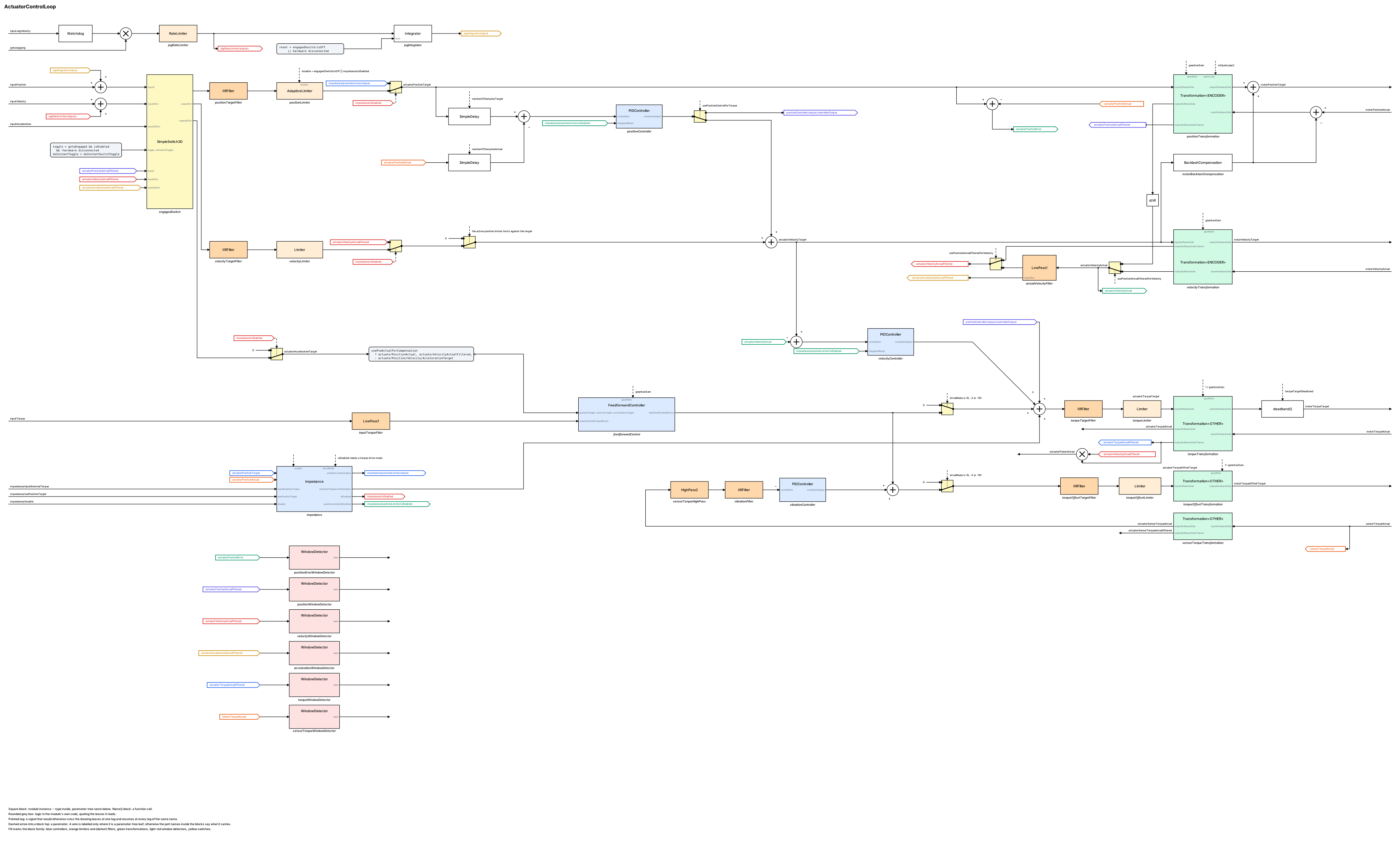
Every sub-module on one sheet. Square blocks are sub-modules — the type inside,
the parameter-tree name below — and grey rounded boxes are logic in the loop’s
own code, quoting the leaves it reads. Fills mark the family: blue
controllers (the Impedance block among them), light orange limiters, darker orange filters, green
transformations, light red window detectors, yellow switches. The
FeedforwardController and Impedance blocks hide several sub-modules each;
only their external ports are named — the feedforward’s inside is drawn in
feedforward-controller.md. The left half is the control system, top to bottom in the
order the code runs; the right half is the motor side, where each DUAL
transformation is one tall block shared by the target lane flowing right to the
drive and the actual lane flowing left from it. A pointed tag is a signal that
would otherwise cross the sheet: it leaves at one tag and resumes at every tag
of the same name.
Signals
Inputs
| Path | Unit | Range | Description |
|---|---|---|---|
inputPosition |
actuator unit | unbounded | The commanded position. Followed only while engaged. |
inputVelocity |
actuator unit per second | unbounded | The commanded velocity, used as feedforward and as the target in a velocity mode. |
inputAcceleration |
actuator unit per second² | unbounded | The commanded acceleration, used by the feedforward path. |
inputTorque |
torque unit | unbounded | An additive torque. Filtered, then routed by driveMode. |
motorPositionActual |
ticks | unbounded | From the drive. |
motorVelocityActual |
ticks per second | unbounded | From the drive. |
motorTorqueActual |
drive unit | unbounded | From the drive. |
sensorTorqueActual |
sensor unit | unbounded | From a separate force or torque sensor, if fitted. |
gotoEngaged |
- | true or false | Follow the input, or track the measured position. |
doInstantSwitchToggle |
- | true or false | Make that transition a step instead of a fade. |
driveMode |
- | drive enumeration | Which mode the drive is in. Decides the torque routing and gates impedance mode. |
gotoJogging |
- | true or false | Add inputJogVelocity to the commanded motion. |
inputJogVelocity |
actuator unit per second | unbounded | The jog speed. Watchdogged: if it stops being written it falls to 0 after a timeout. |
disable |
- | true or false | Disables the loop. |
impedance/inputExternalTorque |
torque unit | unbounded | The external torque for impedance mode. |
impedance/usePositionTarget |
- | true or false | Whether impedance limiting works from the target or the measured position. |
impedance/disable |
- | true or false | Disables impedance mode. |
Outputs
| Path | Unit | Description |
|---|---|---|
motorPositionTarget |
ticks | To the drive. |
motorVelocityTarget |
ticks per second | To the drive. |
motorTorqueTarget |
drive unit | To the drive, in a torque mode only — otherwise 0. |
motorTorqueOffsetTarget |
drive unit | To the drive, in a position or velocity mode only — otherwise 0. |
actuatorPositionTarget |
actuator unit | What the loop decided the axis should do, before conversion. Trace this first when commissioning. |
actuatorVelocityTarget |
actuator unit per second | Zeroed when the position limiter is limiting in the direction of travel. |
actuatorAccelerationTarget |
actuator unit per second² | Zeroed when either limiter is limiting. |
actuatorTorqueTarget |
torque unit | The torque path’s output: the position, velocity and impedance controller torques in every mode, plus the additive torque in a torque mode only. |
actuatorPositionActual |
actuator unit | Where the axis is. |
actuatorVelocityActual |
actuator unit per second | |
actuatorTorqueActual |
torque unit | |
actuatorPowerActual |
power unit | Torque times velocity. |
actuatorPositionError |
actuator unit | Target minus actual. The main health signal for the axis. |
actuatorVelocityError |
actuator unit per second | |
actuatorPositionActualFiltered |
actuator unit | The filtered measurements. These are what the loop uses internally while idle, and what the window detectors watch. |
actuatorVelocityActualFiltered |
actuator unit per second | |
actuatorAccelerationActualFiltered |
actuator unit per second² | |
actuatorTorqueActualFiltered |
torque unit | |
actuatorSensorTorqueActual |
torque unit | The separate sensor, converted to actuator units. |
actuatorSensorTorqueActualFiltered |
torque unit | |
gearboxGain |
- | gearboxLoadSide ÷ gearboxMotorSide. Read it back to check the ratio. |
isEnabled |
- | The loop is running. |
impedance/isEnabled |
- | Impedance mode is active. It requires a torque drive mode — enabling it in a position mode does nothing. |
Parameters
| Path | Unit | Default | Range | Effect |
|---|---|---|---|---|
enable |
- | — | - | Enables the loop. |
gearboxLoadSide |
teeth | — | non-zero | Load-side tooth count. Not checked for zero. |
gearboxMotorSide |
teeth | — | non-zero | Motor-side tooth count. Not checked for zero. |
windowDetectorsEnable |
- | — | - | Turns all six fault detectors on. Leave this on in service. |
usePositionActualFilteredForVelocity |
- | — | - | Derive velocity from the filtered position instead of the drive’s own velocity. |
usePvaActualForCompensation |
- | — | - | Feed the feedforward path the measured motion instead of the commanded motion. |
torqueTargetDeadband |
torque unit | — | 0 upward | Suppresses small torque targets. |
impedance/enable |
- | — | - | Enables impedance mode, subject to the drive being in a torque mode. |
positionController/parameter |
— | — | — | The position PID’s gains and limits. |
positionController/usePositionControlForTorque |
- | — | - | Route the position PID’s output to torque instead of adding it to the velocity target. |
positionController/delayForControlError/numberOfSamplesTarget |
cycles | — | 0 upward | Delays the target before the error is formed, to match the fieldbus round trip. Typically 4 for EtherCAT. |
positionController/delayForControlError/numberOfSamplesActual |
cycles | — | 0 upward | The same for the measurement. |
velocityController/parameter |
— | — | — | The velocity PID’s gains and limits. |
vibrationController/parameter |
— | — | — | The vibration damper’s gains. Its derivative gain is forced to 0 whatever you write. |
Everything else is in the sub-trees — the transformations, the limiters, the six window detectors, the feedforward controller and the backlash compensation. All parameters are persistent and survive a controller restart.
Which sub-trees exist depends on how the loop was built. A loop built
without torque support has no torqueTransformation, no torqueWindowDetector
and no feedforward controller.
The drive modes
driveMode follows mcx::drive::DriveMode, plus a few values specific to this block:
| Value | Mode | What the drive follows |
|---|---|---|
8 |
cyclic synchronous position | motorPositionTarget, with motorTorqueOffsetTarget as additive torque |
9 |
cyclic synchronous velocity | motorVelocityTarget, with motorTorqueOffsetTarget as additive torque |
10 |
cyclic synchronous torque | motorTorqueTarget |
-3 |
cyclic synchronous current | motorTorqueTarget, motor constant in the torque transformation |
-110 / -109 / -108 |
Sensodrive torque / velocity / position | as 10 / 9 / 8 |
0, 1..7 |
other DriveMode values |
treated like a position or velocity mode: no torque command |
The three controllers, leaf by leaf
positionController/, velocityController/ and vibrationController/ have the same shape. Each has a parameter/
folder of gains, an input/ folder of runtime inputs and an output/ folder:
input/ node |
Description |
|---|---|
disable |
The loop writes this every cycle from the engage state and the impedance mode; write it yourself only through the block’s own API. |
integratorFreeze |
Hold the integrator. |
integratorReset |
Zero the integrator; clears itself. |
controllerReset |
Zero every state; clears itself. |
controlError |
The error the module computed this cycle. Published for reading. |
output/ node |
Description |
|---|---|
controllerOutput |
The saturated controller output. |
integratorOutput |
The integrator state. |
derivativeOutput |
The filtered derivative term. |
isEnabled |
parameter/enable && !input/disable. All outputs are zero while this is false. |
<controller>/parameter/
All three controllers share these; the vibration controller ignores derivativeGain (it is forced to zero).
| Node | Default | Description |
|---|---|---|
enable |
0 |
The controller’s own enable. Off by default: nothing is closed until you set it. |
proportionalGain |
0.0 |
P gain. |
integratorGain |
0.0 |
I gain, on the error outside controlErrorDeadBand. Integration stops in the direction that would push further into a saturated output. |
backCalculationGain |
0.0 |
Anti-windup: drives the integrator so the unsaturated output returns to the saturated one. |
derivativeGain |
0.0 |
D gain. |
derivativeFilter |
10.0 |
Bandwidth of the derivative filter. |
controlErrorDeadBand |
0.0 |
Error below which the integrator does not integrate. |
controlIntegrationMin / controlIntegrationMax |
0.0 / 0.0 |
Hard clamp on the integrator state. Both zero means the integrator is clamped to zero — set them before using integratorGain. |
controlOutputMin / controlOutputMax |
-100.0 / 100.0 |
Saturation of controllerOutput. |
Target shaping filters
Four IIRFilter sub-trees shape the outgoing targets. Each is a full IIR of up
to order 6 — enough for two notches plus a lowpass — and each sits in front
of its limiter, which in turn sits in front of the transformation:
| Filter | Shapes | Order in the chain |
|---|---|---|
positionTargetFilter |
the position target | engaged switch → filter → positionLimiter → positionTransformation |
velocityTargetFilter |
the velocity target | engaged switch → filter → velocityLimiter → velocityTransformation |
torqueTargetFilter |
the torque target | torque sum → filter → torqueLimiter → torqueTransformation |
torqueOffsetTargetFilter |
the additive torque | offset sum → filter → torqueOffsetLimiter → torqueOffsetTransformation |
All four default to pass-through (order 1, num[0] = den[0] = 1), so a
loop you have not tuned behaves exactly as it did before these filters existed.
A filter that is switched off is a bypass, not a mute.
IIRFilteron its own outputs zero when it is disabled, whenorderis 0, or whenden[0]is 0 — which in a setpoint path would be a command to zero. This block therefore guards every one of the four: whenever a filter is not actually filtering, the unfiltered signal is passed to the limiter instead. You can disable any of these four safely. That guard is specific to this block; anIIRFilteryou place in a setpoint path yourself has no such protection.
The two torque filters are inside the feedback loops. Their input is the sum of the feedforward and the position and velocity controller outputs, so tuning them changes loop stability. That is exactly what you want from a notch on a mechanical resonance, but treat these as stability parameters, not as cosmetic smoothing. The position and velocity filters shape the reference only and are outside every loop.
Filtering happens before the limiter, and that is deliberate. An IIR response is not amplitude-bounded: a filter placed after a limiter can ring past the limit and hand the drive a target outside the allowed envelope, and it would also decouple the limiters' own limiting flags — which drive the velocity and acceleration zeroing — from the signal actually commanded. The price is that clipping is not smoothed, which only matters in saturation.
Feedforward does not see these filters. The feedforward path taps the setpoints before the filters but after the same limiting, so retuning a filter never changes the feedforward torque. One second-order effect remains:
positionLimiteris adaptive, and its active window is computed from the filtered signal, so a tuned position filter shifts that window slightly and the feedforward tap inherits the shift.
The acceleration target is not filtered.
The vibration damper’s own filter
vibrationFilter is a fifth IIRFilter, in the vibration controller’s
feedback path rather than a target path:
sensorTorqueActual → sensorTorqueHighPass → vibrationFilter → vibrationController
sensorTorqueHighPass is unchanged and still does the DC rejection that decides
what counts as vibration. vibrationFilter sits behind it, pass-through by
default, and is where you put notches to keep higher-frequency content out of
the damper. It is guarded the same way as the four target filters, so switching
it off bypasses it instead of zeroing the feedback.
Remember where the damper’s output goes: it is added to the additive torque channel only, so it is inactive in a torque mode whatever this filter is set to.
Setup
-
Configure the transformations first, under
positionTransformationandvelocityTransformation. Nothing else can be checked until the axis reports its position correctly in engineering units. -
Set
gearboxLoadSideandgearboxMotorSide, and readgearboxGainback. -
With the drive disabled, move the axis by hand and confirm
actuatorPositionActualreads correctly over a long move. -
Set the limiters under
positionLimiterandvelocityLimiterto values the machine cannot be hurt by. -
Set the six window detectors' levels from a trace of normal operation, and set
windowDetectorsEnabletrue. -
Leave
gotoEngagedfalse and enable the drive. ConfirmactuatorPositionTargettracksactuatorPositionActualand the axis does not move. -
Set
positionController/delayForControlError/numberOfSamplesTargetand…Actualto match your fieldbus — 4 samples is typical for EtherCAT. -
Feed
inputPositionthe axis’s current measured position, then setgotoEngagedtrue.Step 8 hands the axis to your setpoint source. If
inputPositiondoes not match where the axis is, the loop will move it there over the fade. Match them first, and keep the limiters tight. -
Leave the four target filters at their pass-through default for now. Tune a notch only once you have measured the resonance you are aiming at.
-
Tune the controllers — go to Tuning.
Tuning
- Get the measurement chain right before touching a gain. Trace
actuatorPositionActualandactuatorVelocityActualat rest and in motion; noise here becomes torque later. - Set the two control-error delays to your fieldbus round trip. Getting these wrong makes the position error look like a lag, and tempts you into gains that oscillate.
- Tune the velocity controller first, then the position controller around it. The usual order: raise proportional gain until the axis is stiff, add integral until steady-state error clears, add derivative only if you must.
- Watch
actuatorPositionErrorthroughout. It is the single best indicator of whether the loop is healthy. - Add feedforward once the feedback loop is stable. It reduces the error the controllers have to work on rather than replacing them.
- Set
usePvaActualForCompensationonly if the feedforward is fighting the commanded motion — normally the commanded motion is the right input. - Set the window detector levels from the error you actually see, with margin. They are your protection, not a diagnostic.
- Re-check everything after a task-rate change: the control-error delays are in cycles, so their meaning in seconds changes with the rate.

The fade is what keeps the axis from stepping at the moment you take control.
| Symptom | Cause | Action |
|---|---|---|
| The axis jumped when engaging | inputPosition did not match the measured position |
Match them before engaging |
| The axis stepped rather than faded | doInstantSwitchToggle is true |
Set it false |
| The axis moves while idle | Something downstream is not respecting motorPositionTarget, or the drive is in the wrong mode |
Check driveMode |
| Nothing moves when engaged | enable is false, disable is true, or the limiters are clamping |
Check isEnabled and the limiters |
| Position error grows with speed | Feedforward is missing or under-tuned, or the control-error delays are wrong | Set the delays first |
| The axis oscillates | Controller gains too high, or the measurement is noisy | Lower the gains; check the measurement filtering |
| The axis oscillates only at one frequency | A structural mode | Use the IIR filter in the transformation, or the vibration controller |
| The vibration controller’s derivative gain does nothing | It is forced to 0 in this version | Use proportional and integral only |
| Torque appears on the wrong output | Expected: the routing follows driveMode |
Check which mode the drive reports |
| The feedforward torque blips to zero for a moment when the drive changes mode | Expected: the routing switches on the commanded mode, a few cycles before the drive reports the new one | Nothing to fix; sequence mode changes at rest if the blip matters |
| The axis received torque twice during a mode change | Should not happen — the two channels are gated so only one is live | Report it |
| Impedance mode does nothing | It requires a torque drive mode | Check driveMode and impedance/isEnabled |
| The axis keeps jogging after the operator lets go | Should not happen — the jog velocity is watchdogged to 0 | Check the writer is really stopping |
| A fault will not clear | The window detectors latch. The reset is not on this block | Assert resetErrors on the parent’s state input — it clears every axis at once |
| Everything is scaled wrongly | The gearbox ratio, or the transformations | Read gearboxGain back and check the transformations first |
| The loop misbehaves after writing a gearbox value | A zero tooth count is not refused here | Read both back |
| A sub-tree I expected is missing | The loop was built without that feature | Fixed when the controller is built |
| The torque detector’s thresholds seem to be in the wrong units | It watches the raw sensor value, unlike the other five | Set its levels from a trace of that signal |
A starting point once the transformations are correct:
gearboxLoadSide       = <from the drivetrain>
gearboxMotorSide      = <from the drivetrain>
windowDetectorsEnable = true
positionController/delayForControlError/numberOfSamplesTarget = 4
positionController/delayForControlError/numberOfSamplesActual = 4
usePvaActualForCompensation = false
Worked configuration — cyclic synchronous position
A drive in mode 8, with a 2000-count encoder behind a 50:1 gearbox, the position loop closed in the drive and the
module supplying the position target and a feedforward torque on the offset channel. Values not listed stay at
their defaults.
| Parameter | Set to | Why |
|---|---|---|
gearboxLoadSide |
50 |
50:1 reduction |
gearboxMotorSide |
1 |
" |
positionTransformation/ticksPerRevolution |
2000 |
encoder counts per motor revolution |
positionTransformation/gainNum, gainDen |
1, 6.283185307179586 |
gain = gainNum / gainDen * ticksPerRevolution ticks per unit of position: 2000 ticks per 2π of motor rotation; the gearbox ratio is applied on top automatically |
velocityTransformation/ticksPerRevolution, gainNum, gainDen |
as above | same scaling for the drive’s velocity unit |
torqueOffsetTransformation/gainNum, gainDen |
drive-specific | actuator torque → the drive’s torque unit; the gearbox ratio is applied automatically |
positionLimiter/enable |
1 |
travel limits on the setpoint |
positionLimiter/lowerLimit, upperLimit |
the travel | " |
velocityLimiter/enable |
1 |
|
velocityLimiter/lowerLimit, upperLimit |
-2.0, 2.0 |
what the mechanism may do |
torqueOffsetLimiter/enable |
1 |
never ask the drive for more than the motor delivers |
torqueOffsetLimiter/lowerLimit, upperLimit |
motor rating | " |
engagedSwitch/fadeInTime |
1.0 |
one second from the actual position onto the setpoint |
feedforwardControl/enable |
1 |
model-based additive torque |
feedforwardControl/externalMass, gravity, … |
the model | see feedforward-controller.md |
positionController/parameter/enable |
0 (default) |
the drive closes the position loop |
velocityController/parameter/enable |
0 (default) |
" |
windowDetectorsEnable |
1 |
|
positionErrorWindowDetector/low, high |
-0.01, 0.01 |
following-error warning |
positionErrorWindowDetector/tooLow, tooHigh |
-0.05, 0.05 |
following-error error |
Operate it with driveMode = 8, then gotoEngaged = 1 once the drive is operational and the transformation is
referenced.
Worked configuration — cyclic synchronous torque, loops closed here
The same actuator in mode 10: the drive follows motorTorqueTarget, and the module closes both loops as a
position-over-velocity cascade.
| Parameter | Set to | Why |
|---|---|---|
transformations, gearbox, limiters, engagedSwitch |
as the position example | |
torqueTransformation/gainNum, gainDen |
drive-specific | actuator torque → the drive’s torque unit |
torqueLimiter/enable |
1 |
the torque channel is now the command |
torqueLimiter/lowerLimit, upperLimit |
motor rating | " |
velocityController/parameter/enable |
1 |
inner loop |
velocityController/parameter/proportionalGain |
tuned | |
velocityController/parameter/integratorGain |
tuned | |
velocityController/parameter/controlIntegrationMin, controlIntegrationMax |
-10, 10 |
must be set — both at zero clamps the integrator to zero |
velocityController/parameter/controlOutputMin, controlOutputMax |
motor rating | saturation of the controller torque |
positionController/parameter/enable |
1 |
outer loop |
positionController/parameter/proportionalGain |
tuned | velocity per unit of position error |
positionController/parameter/controlOutputMin, controlOutputMax |
-2.0, 2.0 |
the outer loop may not ask for more than velocityLimiter allows |
positionController/usePositionControlForTorque |
0 (default) |
cascade, not a direct position-to-torque loop |
feedforwardControl/enable |
1 |
in a torque mode the feedforward goes out on motorTorqueTarget |
The feedforward moves from the offset channel to the torque channel by itself when driveMode changes to 10.
Worked configuration — impedance
Torque mode as the torque example, and the actuator made compliant to an external controller writing
impedance/inputExternalTorque, with a soft fence of ±0.1 around wherever the actuator is:
| Parameter | Set to | Why |
|---|---|---|
| as the torque example | ||
impedance/enable |
1 |
|
impedance/externalTorqueLimiter/enable |
1 |
bound what the outside may ask |
impedance/externalTorqueLimiter/lowerLimit, upperLimit |
motor rating | " |
impedance/positionLimiter/enable |
1 |
the fence |
impedance/positionLimiter/lowerLimit, upperLimit |
-0.1, 0.1 |
the fence, around the actual position (impedance/usePositionTarget = 0) |
positionController/parameter/proportionalGain |
tuned | this is the stiffness of the fence: only the position controller pushes back, on the undelayed error and without integrator |
impedance/isEnabled confirms the mode is active; it needs driveMode = 10, impedance/enable and
impedance/disable = 0. While it is active getPositionClosedLoop() reports the loop as open.
Limits and errors
| Limit | Set by | What happens | Reported |
|---|---|---|---|
| Position and velocity | positionLimiter, velocityLimiter sub-trees |
Targets are clamped. The velocity target is zeroed when the position limiter is limiting in the direction of travel, and the acceleration target when either is limiting | The limiters' own outputs |
| Target filter switched off | Guarded in this block | The unfiltered signal is passed on. A bare IIRFilter would output 0 here |
The filter’s isEnabled |
| Target filter overshoot | The limiter downstream of it | Clamped, because every target filter runs before its limiter | The limiters' own outputs |
| Fault detection | The six window detector sub-trees | Latching warning and error flags per quantity | Each detector’s noError |
| Fault reset | The parent’s state input | This block has no reset path of its own. Inside AxesControl the reset arrives through its state channel and clears every actuator at once. A standalone loop can be reset only by an application |
Not reported |
| Jog velocity loss | Watchdog | Falls to 0 if the writer stops | Not reported |
| Engage transition | The engaged switch sub-tree | Faded, unless doInstantSwitchToggle |
Not reported |
| Additive torque routing | driveMode |
Exactly one of the two torque outputs carries it; the other contribution is 0. The gate follows the commanded mode, so on a change into a torque mode the additive torque drops out for the few cycles the drive takes to report the new mode | Both outputs |
| Impedance mode | driveMode |
Silently inactive unless the drive is in a torque mode | impedance/isEnabled |
| Gearbox ratio | Nothing | A zero tooth count is not refused and makes the conversion invalid | gearboxGain |
| Values that are not numbers | Nothing | Not checked anywhere in this block | Not reported |
| Control error delays | Fixed in cycles | Their meaning in seconds changes with the task rate | Not reported |
| Vibration controller derivative | Fixed | Forced to 0 every cycle, whatever you write | Read it back |
| Features present | Fixed at build time | Torque, feedforward, sensor torque and the two controllers are each compiled in or out | Missing sub-trees |
| Axis count | Fixed | One axis per instance, always | Not reported |
This block logs nothing itself. Sub-modules below it may log — the transformation’s transducer logs during referencing. Every other condition above shows as a value on a trace, or not at all.
Verified against motorcortex-control3 3.32.1 (340db23).