Transformations
11 minute read
The drive counts in its own units: encoder ticks, rpm, or thousandths of its rated torque. The application works in rad or m, rad/s and Nm at the load. A transformation converts between the two, in both directions, and the gearbox ratio is part of it.
Using the standard robot GUI?
The robot and machine GUIs show the same parameters on their axis settings tab, and save them with Save Settings. See Robot axis settings.
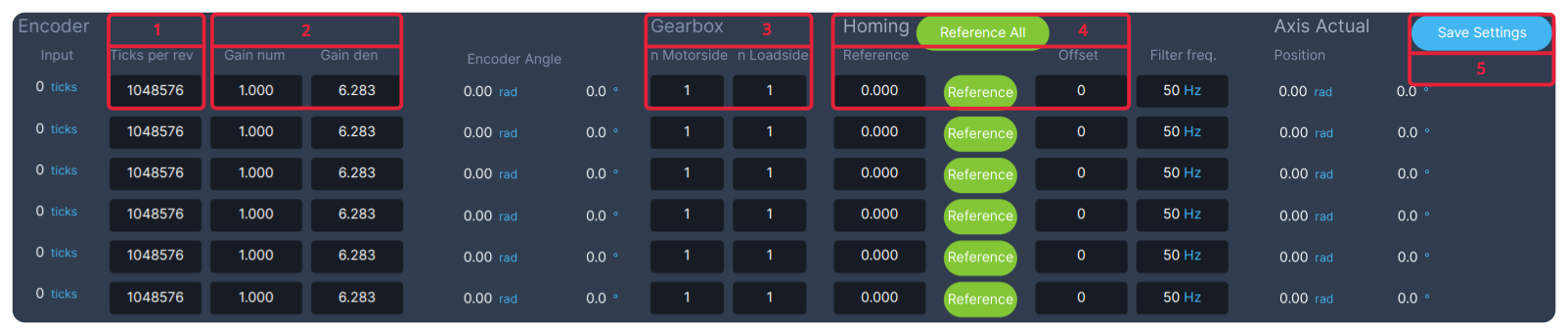
- Ticks per rev:
ticksPerRevolutionof the position transformation, the encoder resolution. - Gain num and Gain den:
gainNumandgainDen.1and6.283count in rad; a negative Gain num reverses the direction. - n Motorside and n Loadside: the gearbox,
gearboxMotorSideandgearboxLoadSide. - Homing: type the position the axis is at in Reference and press Reference, or Reference All for every axis. The resulting Offset in ticks is stored for you.
- Save Settings: saves the changes, so they survive a restart.
This is what happens to a position reading:
Every transformation has the same three settings under its transducer/:
| Parameter | What it does | Default |
|---|---|---|
ticksPerRevolution |
Drive units per motor revolution, for example the encoder resolution | 1 |
gainNum, gainDen |
Scale the result: the gain is ticksPerRevolution × gainNum / gainDen. A negative gainNum reverses the direction |
1, 1 |
offset |
Drive value at the zero position. Only the position transformation needs one | 0 |
The gearbox ratio gearboxLoadSide / gearboxMotorSide is set once per axis and applies to position, velocity and torque. Leave both at 1 if the drive already works at the load side.
Warning
Give position, velocity and torque the same direction. If one of them has the opposite sign, the controllers push the wrong way and the axis can run away. Check each one before you enable the axis.
Pick a transformation; each tab shows its parameters and an example.
The position transformation turns the ticks the drive reports into the axis position at the load, and turns the position target back into ticks. All paths are under root/AxesControl/actuatorControlLoops/actuatorControlLoopNN/.
Set it up in this order; click a step to jump to it.
Enter the encoder and gearbox
Three things turn ticks into a position: the encoder resolution, the unit you count in, and the gearbox. The first two are under positionTransformation/transducer/, the gearbox is on the control loop itself. Together they make the gain: ticksPerRevolution × gainNum / gainDen ticks per unit at the motor, divided by the gearbox ratio at the load.
| Parameter | What it does | Default | Rotary axis in rad | Linear axis in m |
|---|---|---|---|---|
ticksPerRevolution |
Encoder ticks per motor revolution | 1 |
1048576: 20-bit encoder |
524288: 19-bit encoder |
gainNum, gainDen |
Motor revolutions per unit, as a fraction. A negative gainNum reverses the direction |
1, 1 |
1, 6.283185: one revolution is 2π rad |
1, 1: count in revolutions |
gearboxLoadSide, gearboxMotorSide |
Motor revolutions per revolution, or metre, at the load. Leave at 1 if the drive applies the gearbox itself |
1, 1 |
80, 1: 80:1 gearbox |
100, 1: 100 motor revolutions per metre |
offset |
Ticks at the zero position | 0 |
Set by homing | Set by homing |
- Rotary axis: the standard robot configuration uses these values, with a 1:1 gearbox.
- Linear axis: a motor turns a spindle with a 10 mm pitch through two pulleys of the same size, so the carriage moves 10 mm per motor revolution. Counting in revolutions and setting the gearbox to 100:1 makes the axis read metres.
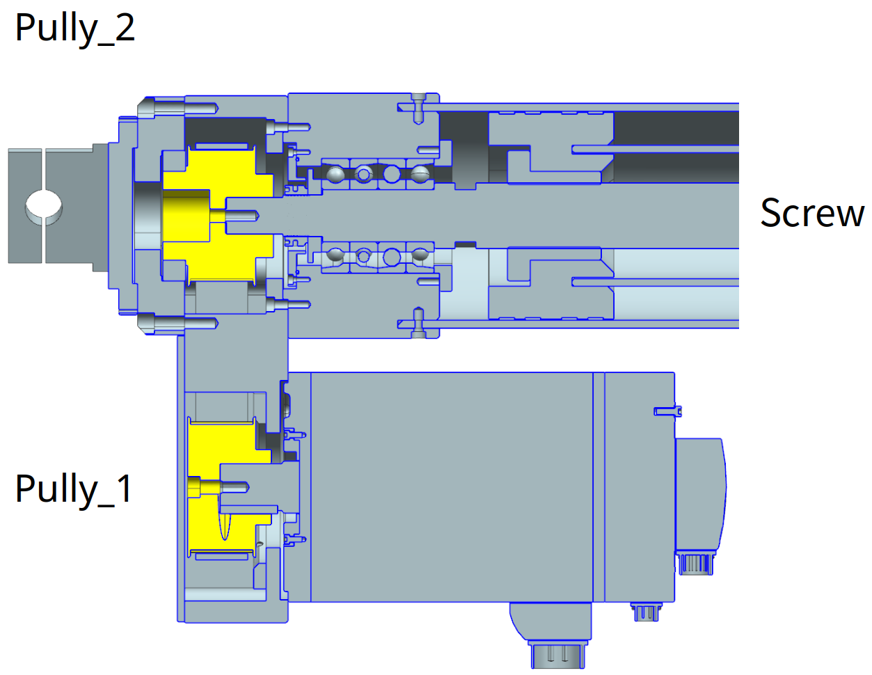
To check your numbers, read back positionTransformation/transducer/gain, the ticks per unit at the motor, and move the axis a known distance while you watch actuatorPositionActual. The positions of all axes together are in root/AxesControl/axesPositionsActual.
Check the direction
Position, 3D view and controllers all assume the axis counts up when it moves in its positive direction. If it counts down, the 3D view moves the wrong way. If position, velocity and torque disagree in sign, a controller pushes the axis away from its target instead of towards it.
- Engage the axis and jog it a small distance in the positive direction.
- Watch
actuatorPositionActual, and the 3D view if your application has one. Both must move the same way as the real axis. - If they move the other way, make
gainNumnegative. Do the same in the velocity and torque transformations, so all three agree.
Set the zero position
Right after start-up the encoder’s ticks say nothing about where the axis is. Homing, also called referencing, fixes that: with the axis at a known position, the transducer stores the offset that makes it read that position:
offset = ticks at that moment − reference position × gain
From then on the axis reads the right position everywhere.
- Move the axis to a position you know, for example straight up at 0°.
- Reference the axis. In the standard robot GUI: enter the position in Reference on the axis settings tab and press Reference, or Reference All for every axis. See Homing.
- Check that
actuatorPositionActual, and the 3D view, now match the real axis. - Save the parameter tree, so the offset survives a restart.
Keep the position after a power cycle
You only need this for an encoder that does not keep its position without power, such as one that only counts within one turn. Without it you home the axis after every power cycle. Persistence stores the position at power off and checks it at start-up:
Parameter under positionTransformation/transducer/ |
What it does | Default |
|---|---|---|
enablePersistence |
1 stores the ticks and offset in persistence.bin and checks them at start-up |
0 |
deltaTicksMax |
The largest movement, in ticks, that still counts as the same position. The standard robot configuration uses 10000 |
-1 |
deltaTicks |
Output: how far the encoder moved while the power was off | |
enableSingleTurnCounter |
1 counts the whole turns of an encoder that restarts at 0 every turn |
0 |
- Set
enablePersistenceto1anddeltaTicksMaxto the movement you accept, then save the parameter tree. - Home the axis.
- Switch the controller off and on, and read
deltaTicks: it shows how far the encoder moved in between.
If deltaTicks is larger than deltaTicksMax, leaving Off raises the emergency stop ES_NOT_REFERENCED (508). Home the axis again to clear it.
The velocity transformation turns the drive’s Velocity actual value into rad/s or m/s at the load, and the velocity target back into drive units. It has no offset. Paths are under actuatorControlLoopNN/velocityTransformation/transducer/.
Using the standard robot GUI?
The velocity transformation is under Motor Velocity on the axis settings tab. Press Save Settings to keep your changes. See Robot axis settings.
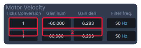
- Ticks Conversion:
ticksPerRevolution. - Gain num and Gain den:
gainNumandgainDen. The example,-60and6.283, is a drive that counts in rpm, with the direction reversed.
Choose the values from the unit the drive uses:
| Drive unit | ticksPerRevolution |
gainNum |
gainDen |
|---|---|---|---|
| Revolutions per second | 1 |
1 |
6.283185 (2π) |
| rpm | 1 |
60 |
6.283185 |
| 0.001 rpm | 1000 |
60 |
6.283185 |
| Encoder ticks per second | the encoder resolution | 1 |
6.283185 |
The gearbox ratio of the axis applies here too. Give gainNum the same sign as in the position transformation.
Velocity from the position
To derive the actual velocity from the position instead of the drive’s velocity value, set actuatorControlLoopNN/usePositionActualFilteredForVelocity to 1. Use this when the drive’s velocity value is not mapped in its PDOs.
Three drive entries carry a torque: Target torque, Torque offset and Torque actual value. Two transformations convert them, and they must have the same settings:
| Transformation | Converts |
|---|---|
torqueTransformation |
The torque target and the actual torque |
torqueOffsetTransformation |
The torque offset, the feedforward torque sent in CSP and CSV |
Using the standard robot GUI?
Both transformations are on the axis settings tab: torqueTransformation under Motor Torque, torqueOffsetTransformation under Motor Torque Offset. Press Save Settings to keep your changes. See Robot axis settings.

- Gain num and Gain den, in both panels:
gainNumandgainDen. The example,1000and0.640, is a motor rated at 0.64 Nm.
The other fields show the values on either side: Motor Torque (ticks) and Axis Torque (Nm) are motorTorqueActual and actuatorTorqueActual; Axis TorqueOffset (Nm) and Motor Offset Torque (ticks) are actuatorTorqueOffsetTarget and motorTorqueOffsetTarget.
CiA402 drives usually count torque in thousandths of the motor’s rated torque. Then the gain is 1000 / rated torque: set gainNum to 1000 and gainDen to the rated torque in Nm. For a motor rated at 0.64 Nm, gainNum 1000 and gainDen 0.64. Leave ticksPerRevolution at 1.
The gearbox works the other way round for torque: a 100:1 gearbox turns 1 Nm at the motor into 100 Nm at the load. The transformation takes care of that from the axis’s gearbox ratio. Give gainNum the same sign as in the position transformation.
Check it
Hold the axis still against gravity, or push it gently by hand while it is engaged, and read actuatorTorqueActual in Nm. It should have the sign of the force and a plausible size.
A joint torque sensor measures the torque at the load directly, where the motor torque is only an estimate. The sensor torque transformation turns its value into Nm. It works in one direction only, from the sensor to the application, and the gearbox ratio is not applied. Paths are under actuatorControlLoopNN/.
Using the standard robot GUI?
The sensor torque transformation is under Torque Sensor Calibration on the robot GUI’s Compliance tab.

- Offset, GainNum, GainDen:
transducer/offset,transducer/gainNum,transducer/gainDen. - Ref and the Ref button:
referenceLoadSide, and the calibration triggersetHardwareReference. - Sensor Torques: the calibrated torque in Nm. Static Grav. Tq.: the gravity torque the robot calculates for its current pose.
To calibrate in the GUI: set GainNum and GainDen, put the robot in a still pose, copy Static Grav. Tq. into Ref, press the Ref button, and press Save Settings.
Enter the gain
Link the sensor’s value to sensorTorqueActual, then tell the transformation how many sensor units make one Nm. The parameters are under sensorTorqueTransformation/:
| Parameter | What it does | Default |
|---|---|---|
transducer/gainNum, transducer/gainDen |
Sensor units per Nm, as a fraction. A negative gainNum reverses the sign |
1, 1 |
referenceLoadSide |
The torque in Nm the sensor should read when you calibrate | 0 |
transducer/offset |
Sensor value at zero torque, stored by the calibration | 0 |
Leave the gain at 1, 1 if the sensor already reports Nm.
Check the sign
A sensor with the wrong sign reports every torque in the wrong direction. Engage the axis and hold it still in a pose where gravity loads the joint: the motor then carries the same torque as the sensor, so actuatorSensorTorqueActual must have the same sign as actuatorTorqueActual. If it has the opposite sign, make transducer/gainNum negative.
Calibrate the zero
A torque sensor rarely reads exactly zero at zero torque. Calibration measures its offset in a pose where you know the torque on the joint, and stores it:
offset = sensor value − referenceLoadSide × gain
- Put the axis in a still pose where you know the torque on the joint. On a robot that is the gravity torque, in
root/ManipulatorControl/idJointTorque/actual/gravity. - Write that torque to
sensorTorqueTransformation/referenceLoadSide. - Set
setHardwareReferenceinsensorTorqueTransformation/transducer/referencing/:fromStateto1, then back to0. - Check that
actuatorSensorTorqueActualnow reads the known torque, then save the parameter tree.
Next: Set the limiter.