Add a device
5 minute read
Your application talks to its drives and I/O modules over EtherCAT. This page walks you through adding one device to the application’s EtherCAT configuration with the ECAT tool. The example is a Beckhoff EP2316-0003 digital I/O module, added in a domainA domain is a group of EtherCAT devices whose data Motorcortex exchanges together. Each domain can be simulated or switched off on its own. of its own next to the devices the application already has. Click a domain for more.
Before you start
- An application is deployed and running on the controller: see Deploy an application.
- You have an EtherCAT device and a controller with an EtherCAT port: a Generic Control Case (GCC), an industrial PC or a Raspberry Pi. A virtual machine has no EtherCAT port to connect a device to.
Warning
Connect and power the device as its supplier’s instructions say. Wrong wiring can damage the device or the controller.
Connect the device’s EtherCAT input to the controller’s EtherCAT port, or to the last device already on the bus. On a GCC, your PC goes into the ENET port and the EtherCAT cable into ECAT1.
Open the ECAT tool and connect
The ECAT tool runs in your browser and reads and writes the EtherCAT configuration on the controller, so it needs a connection first.
-
Log in to motorcortex.io with your
EmailandPassword, and pressLog in. No account yet? Register first. -
In the sidebar, under
Tools, clickEcat. The ECAT tool opens in a new browser tab. -
Open the main menu ( ) at the top left and choose
Connection.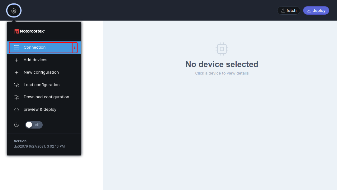
-
In
Host, entercontroller_ip_addressThe IP address of your controller. In most cases 192.168.2.100.. LeaveTLSon and theRequestandReceiveports as they are, unless your controller was set up with other ports. Fill inUsernameandPasswordonly if your controller asks for a log-in.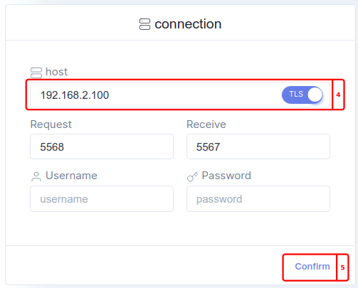
-
Press
Confirm.
Fetch the current configuration
Start from the configuration the controller runs now, so you add to it instead of replacing it.
-
Press
Fetchat the top right. TheDomainslist on the left fills with the domains and devices of the configuration on the controller. -
Check the
GCCdomain. It holds the safety I/O of the Generic Control Case: the EK1914 and the EL6910. On a GCC, keep it as it is. On any other controller these devices are not on your bus: switch the domain off with its checkbox ( ,Include in Ethercat Message). Leave the other domains as they are.
Add a domain and the device
Your own devices go into a domain of their own. That way you can simulate them or switch them off without touching the rest of the bus.
-
Press (
Add Domain) next toDomains.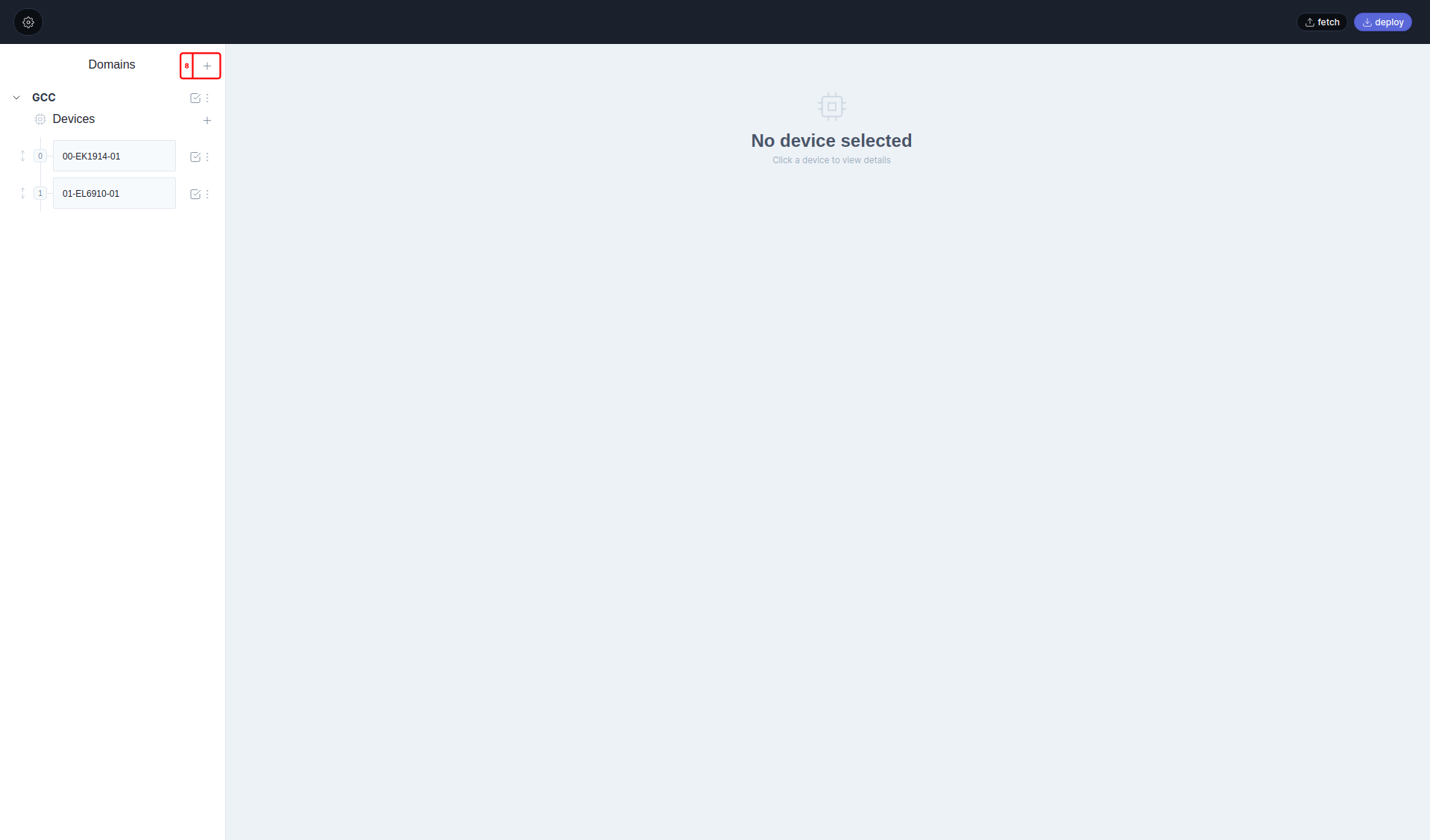
-
Click the new domain, which is called
Untitled, and give it aNamesuch asIO. LeaveSimulationoff: this domain talks to a real device. -
In the new domain, press (
Add Devices) next toDevices. -
On the
From Scantab, pressScan Bus. The list shows every device on the bus, by its position.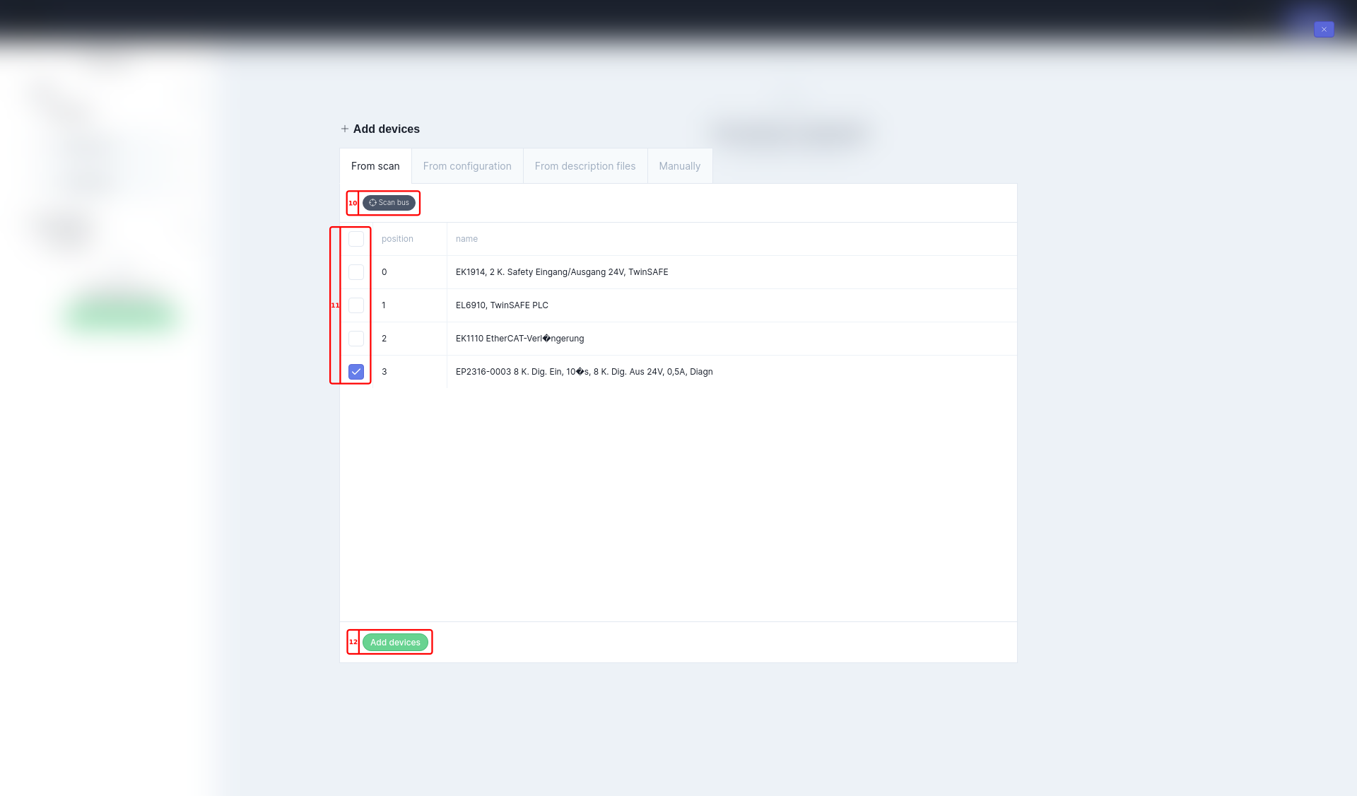
-
Tick only your new module. The devices before it, on a GCC the EK1914, the EL6910 and the EK1110 extension, belong to the existing setup; leave them unticked.
Load the device description
The scan tells the tool which device it found, but not which data the device exchanges. That is in the device’s ESI fileAn ESI (EtherCAT Slave Information) file is an XML file from the device’s supplier. It describes the device: its identity, its process data and its settings.
: with it, the tool fills in the device’s PDOsA PDO (process data object) is a block of values a device exchanges with the controller every cycle. The rxPDO carries data to the device, such as outputs; the txPDO carries data from it, such as inputs.
for you. motorcortex.io keeps ESI files for many devices in its ESI Database.
Note
Applying an ESI file changes the device’s settings: its type, its name if it has none, missing PDOs are added, PDOs are sorted by index, and every entry gets its name, group, type and bit length. The tool asks you to confirm first.
-
Still in the
Add Devicesdialog, tickApply ESI from databaseand confirm. Then pressAdd Devices. -
Click the new device and open its
rxPDOandtxPDOtabs. The module’s output channels are in the rxPDO, its input channels in the txPDO. -
Are the tabs empty? Then the database has no ESI file for this device. Open the device’s
Settingstab and pressUpload ESI fileto load the file from the device’s supplier.
Deploy the configuration
Warning
Deploy restarts the application on the controller with the new EtherCAT configuration. Anything the application is driving stops. Make sure the machine is in a safe state first.
- Press
Deployat the top right. The button showsCompletedwhen the controller has the new configuration.
The application exchanges data with real devices only when it runs in production mode. In simulation mode it uses simulated values instead. The mode is set in the config package: see Mode in config.json.
If a device’s own memory is too small for its description, you can load that description from a file instead: see Custom SII firmware.
Link the device to the application
The module is on the bus now, but nothing in the application reads its inputs or sets its outputs yet. To use a channel, link it to a Motorcortex parameter: see I/O devices in Configure your application. For servo drives, see CiA402 drives.