Simulating devices
5 minute read
An application can run on real EtherCAT devices, on simulated ones, or on a mix. You choose with the system mode in config.json and the Simulation switch of each domain.
no hardware needed
"Mode": "Simulation"
Every device is simulated, whatever its domain’s switch says.
the real machine
"Mode": "Production"
Every domain with Simulation off runs on the real bus.
some real, some simulated
"Mode": "Production"
Domains with Simulation on are simulated; the others run on the real bus.
How a simulated device is linked
Every drive entry can carry two links. The production link connects it to the application and is always there. The simulation link connects the same entry to the simulator and only counts while the device is simulated. The data still passes through the device’s entries, so the rest of the application cannot tell a simulated drive from a real one.
This map shows one axis of the standard robot configuration. Paths starting with …/ are under root/AxesControl/actuatorControlLoops/actuatorControlLoopNN/, where NN is the axis number; the other paths start with root/. Array parameters such as DriveLogic/driveOpMode and Simulator/targetPosition take the channel of the axis: 0 for the first axis, 1 for the second, and so on.
The control word, mode and status word have no simulation link. A simulated axis gets a simulated drive in the drive logic instead, through the device’s Link Simulation described in the Simulation tab.
Set up each mode
Start with Simulation to build the application without hardware, then Production for the real machine. Mixed combines the two, so it assumes you know both.
Run without hardware
-
In config.json, set the system mode:
"Mode": "Simulation"Every domain is now simulated. The domain’s Simulation switch in the Domain Configuration Panel makes no difference in this mode.
-
In the link files, the groups with
"SystemMode": "Simulation"or"All"apply. Use aSimulationgroup to override what has no hardware behind it, for example a physical emergency stop. -
Give each drive a Link Simulation: open the device’s Settings tab and link it to
root/DriveLogic/driveSimulation, with the channel of the axis. This tells the drive logic to simulate the drive.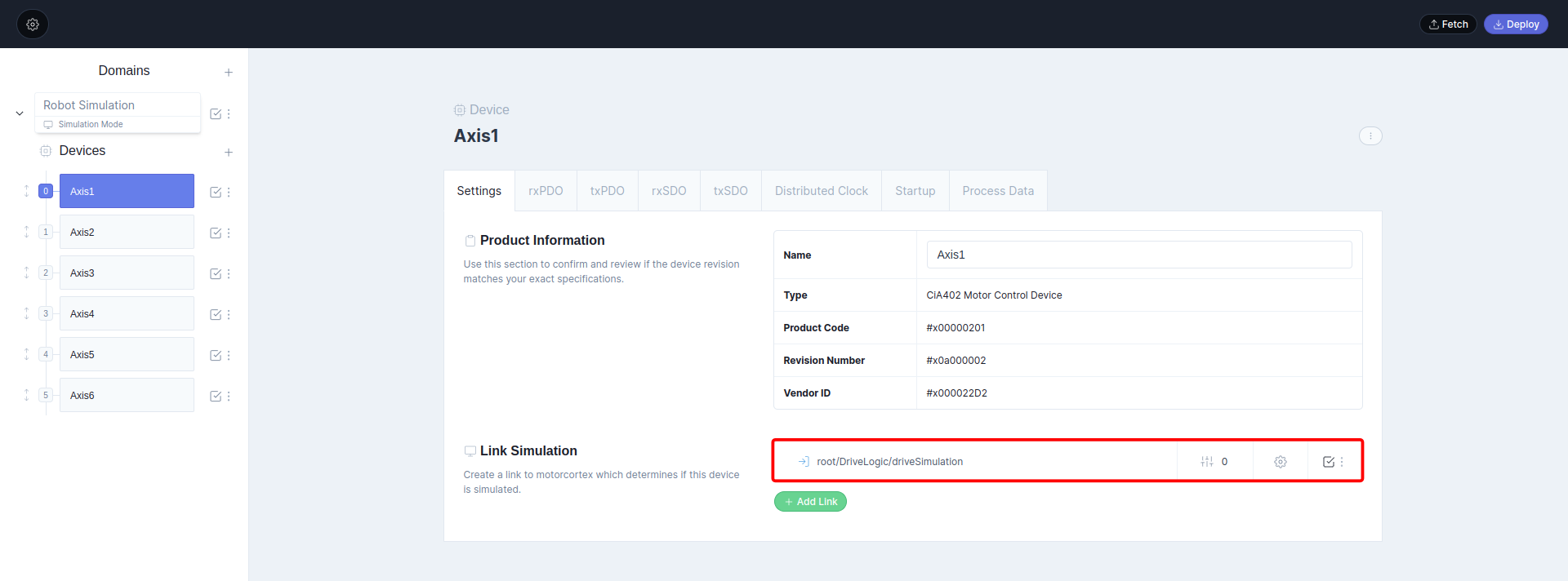
Warning
Give every device its own channel. If two devices share a channel, the axis whose channel is missing is not simulated in the drive logic.
-
Add the simulation links to the drive entries, as on the right of the link map: the targets go to
root/Simulator/targetPosition,targetVelocityandtargetTorque, and the actual values come frompositionValue,velocityValueandtorqueValue. Use the channel of the axis.Open the link’s properties with and switch Simulation on. The turns blue: the link only applies while the device is simulated.

Deploy the configuration and start the application: it runs on the simulator.
Run on the real machine
-
In config.json, set the system mode:
"Mode": "Production" -
In the link files, the groups with
"SystemMode": "Production"or"All"apply. -
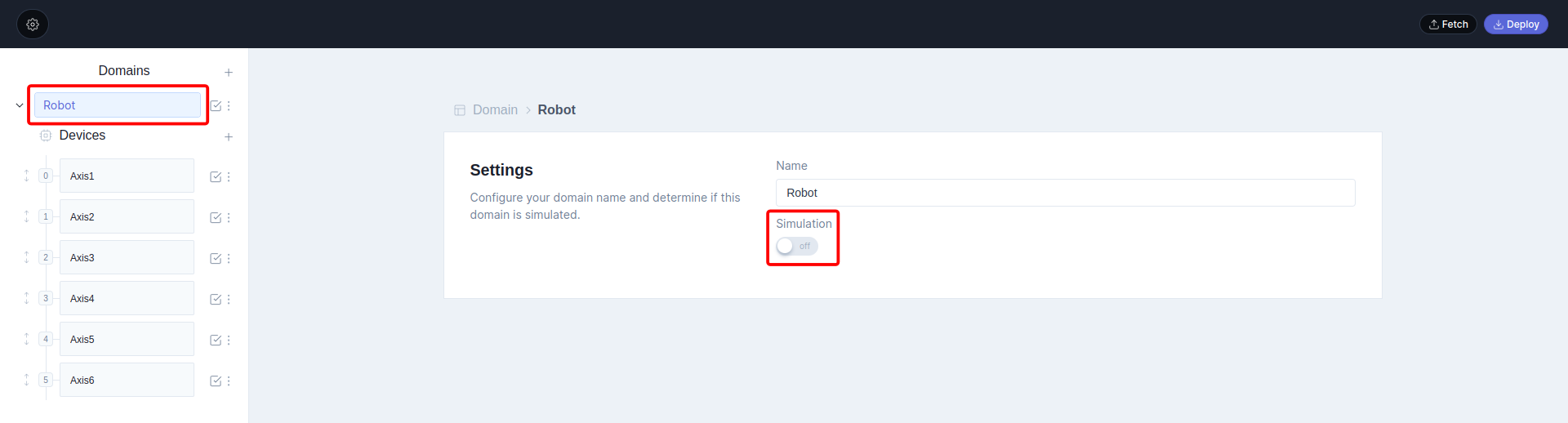
In the Domain Configuration Panel, switch Simulation off for every domain.
-
Link every drive entry to the application, as on the left of the link map. Use the axis number in
actuatorControlLoopNNand the channel of the axis for array parameters.
The torque sensor has a manufacturer-specific index. Look it up in your drive’s ESI file.
Simulation links can stay in place: in production mode they are ignored unless the device’s domain is simulated.
Deploy the configuration and start the application: it runs on the real drives.
Older version: Robot App v1 production mode.
Simulate some devices on the real machine
-
In config.json, set the system mode to production:
"Mode": "Production" -
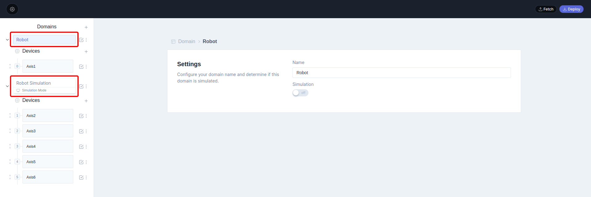
In the Domain Configuration Panel, put the devices you want to simulate in their own domain and switch its Simulation on. Keep the real devices in a domain with Simulation off.
-
Set up the simulated domain’s devices as in the Simulation tab, steps 3 and 4, and the real domain’s devices as in the Production tab, step 4.
Because every entry can carry both links, one configuration covers all three modes. To move a device between real and simulated, move it to the other domain.