Domains configuration panel
10 minute read
The domains panel on the left of the ECAT tool lists your domainsA domain is a group of EtherCAT devices whose data Motorcortex exchanges together. Each domain can be simulated or switched off on its own. and the devices in each. Here you add domains and devices, set where each device sits on the bus, and choose per domain whether it runs on the real bus or is simulated.
Why devices are grouped in domains
Every device belongs to a domain. One domain for the whole bus works. Several domains let you treat parts of the bus differently:
- Simulate a part. In production mode, a domain with
Simulationon is simulated while the other domains run on the real bus. See Simulating devices. - Switch a part off. A domain you exclude is left out of the configuration, with all its devices.
- Run a part slower. With a
Frequency Dividerof 2, the EtherCAT master exchanges the domain’s data every second cycle instead of every cycle.
A new configuration starts with one domain called Default.
Add devices
Press Add your first devices in an empty panel, the
next to Devices in a domain, or Add Devices in the main menu. The Add Devices window has four tabs, one for each place the devices can come from. Click a tab in the diagram to open its steps.
Each tab lists the devices it found, all ticked. Add Devices adds the ticked ones.
Add the devices on the bus
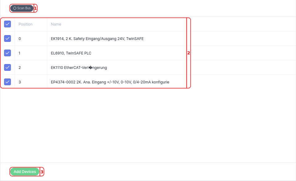
The controller scans the bus and lists every device it finds, at its position and with the process data the device reports. Use this tab when the devices are connected and powered.
- Press
Scan Bus. It needs aHostinConnection. - Every device found is ticked. Untick the ones you do not want to add.
- Tick
Apply ESI from databaseto complete the devices from the ESI database of motorcortex.io, and confirm. This needs your motorcortex.io log-in. - Press
Add Devices.
Add devices from a configuration
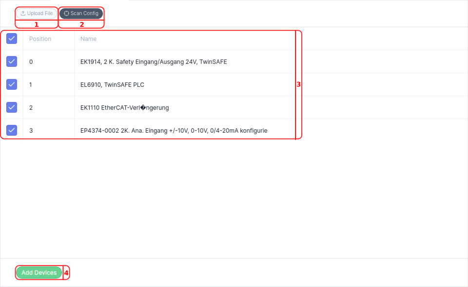
Take devices from another EtherCAT configuration, complete with their process data, SDOs, start-up list and links. Use this tab to reuse devices you configured before.
- Press
Upload Fileto read the devices from a configuration file on your PC, such as amaster.xml. - Or press
Fetchto read them from the configuration on the controller. - Every device found is ticked. Untick the ones you do not want to add.
- Press
Add Devices.
Add devices from ESI files
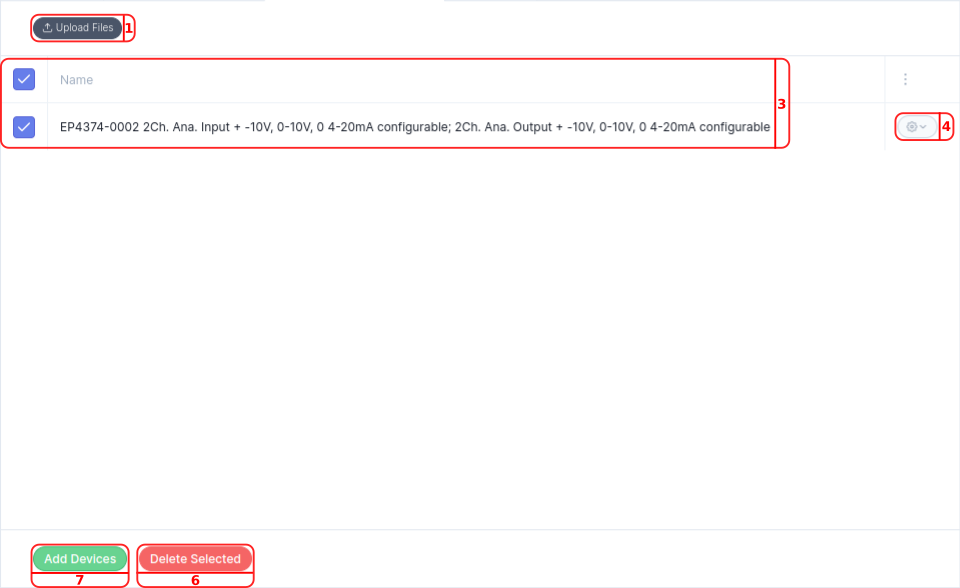
An ESI file from the device supplier describes one or more devices, with their identity and process data. Use this tab to prepare a configuration before the devices are connected. The tool gives each device the position of its place in the domain; check it afterwards.
-
Press
Upload Filesand choose one or more ESI files. -
In the
Select Deviceswindow, tick the devices you want, by name and revision, and pressSelect.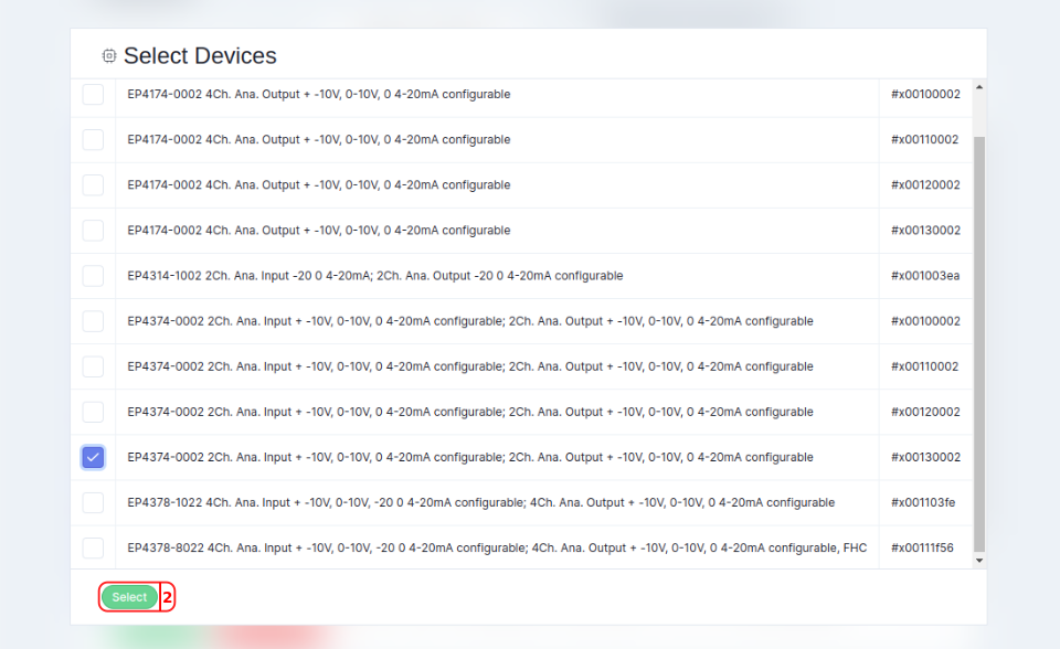
-
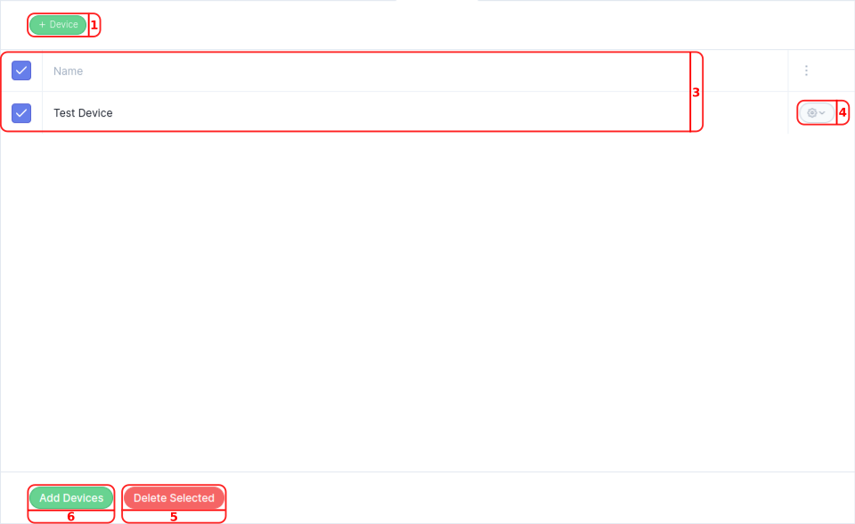
The tab lists the devices you selected, all ticked. Untick the ones you do not want to add.
-
Open the menu next to a device ( ) to
EditorDeleteit.Editopens theDevicewindow, where you change its identity and pressSave.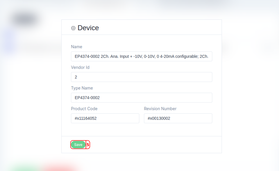
-
Delete Selectedremoves the ticked devices from the list. -
Press
Add Devices.
Add a device by hand
Type in the identity of a device, when you have neither the device nor its ESI file at hand. The device gets no process data this way: load its ESI file later in the device’s Settings tab.
-
Press
Device. -
In the
Devicewindow, fill inName,Vendor Id,Type Name,Product CodeandRevision Number, and pressSave.Vendor Id,Product CodeandRevision Numbertake a decimal number, or a hexadecimal one written with#x, such as#x0000000f. The device gets the position after the highest one in use.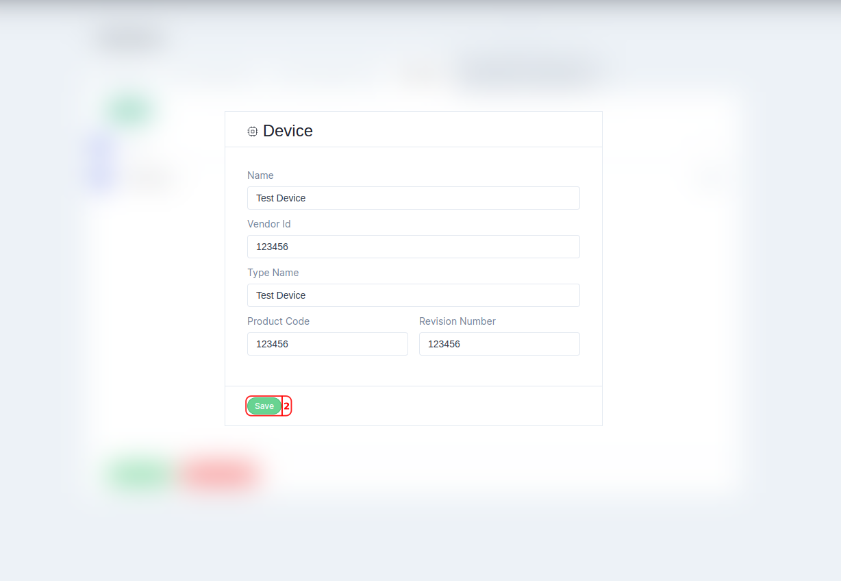
-
Repeat for more devices. Untick the ones you do not want to add.
-
Open the menu next to a device ( ) to
EditorDeleteit. -
Delete Selectedremoves the ticked devices from the list. -
Press
Add Devices.
Work with the devices in a domain
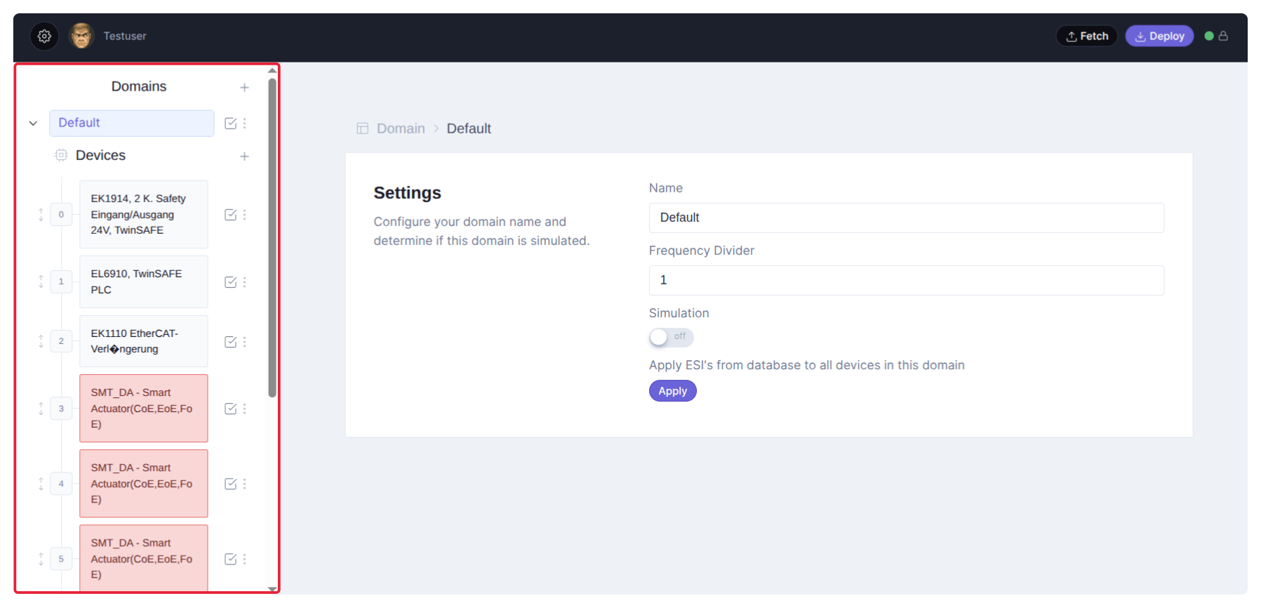
- The number in front of a device is its position on the bus. It turns red when two devices share a position. See Set a device’s position.
- A device name turns red when two devices have the same name. Give every device its own name.
- Click a device to open it in the device panel.
- The checkbox (
,
Include in Ethercat Message) switches a device on or off. A device that is off stays in the tool, but the controller leaves it out. - The menu (
,
More Actions) hasAdd, which opensAdd Devicesto insert devices after this one,Clone, which copies the device to the position after the highest one in use, andDelete. - Drag a device by its handle to change its order or to move it to another domain.
Set a device’s position
The controller finds each device in the configuration by its position. It must match where the device is on the real bus. You can give it as a bus position, such as 3, or as an alias and a position after it, such as 1:0.
Address by bus position
The bus position counts the devices along the cable, starting at 0 for the device next to the controller. It is the default, and what Scan Bus fills in. When you add, remove or rewire a device, the positions of the devices behind it change, and the configuration no longer matches the bus.
-
Open the cockpit terminal of the controller.
-
List the devices on the bus:
mcx-intel:~$ ethercat slaves
0  0:0   OP     +  EK1914, 2 K. Safety Eingang/Ausgang 24V,  TwinSAFE
1  0:1   OP     +  EL6910, TwinSAFE PLC
2  0:2   PREOP  +  EK1110 EtherCAT-Verl�ngerung
3  0:3   OP     +  SMT_DA - Smart Actuator(CoE,EoE,FoE)
4  0:4   OP     +  SMT_DA - Smart Actuator(CoE,EoE,FoE)
5  0:5   OP     +  SMT_DA - Smart Actuator(CoE,EoE,FoE)
6  0:6   OP     +  SMT_DA - Smart Actuator(CoE,EoE,FoE)
7  0:7   OP     +  SMT_DA - Smart Actuator(CoE,EoE,FoE)
8  0:8   OP     +  SMT_DA - Smart Actuator(CoE,EoE,FoE)
9  0:9   PREOP  +  SMT_IO - Smart Actuator
10  0:10  OP     +  EP2328-0001 4 K. Dig. Ein, 3ms, 4 K. Dig. Aus 24V, 2A, M8
The first column is the bus position.
-
In the domains panel, type each device’s bus position in the field in front of its name.
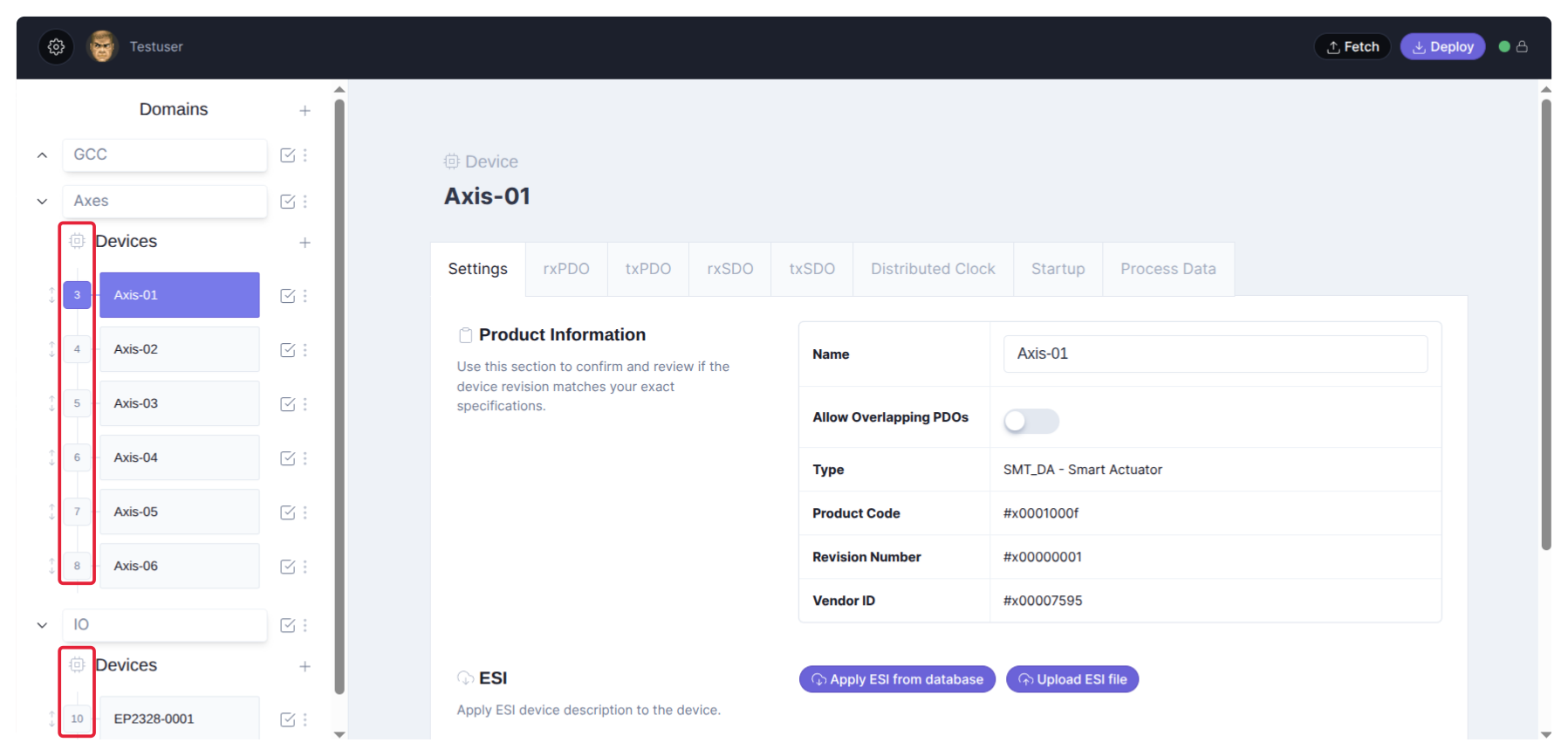
What the columns mean
3  0:3  OP     +  SMT_DA - Smart Actuator(CoE,EoE,FoE)
|  | \- Decimal relative position to the last
|  |       slave with an alias address set.
|  \- Decimal alias address of this slave (if set),
|     otherwise of the last slave with an alias set,
|     or zero, if no alias was encountered up to this
|     position.
\- Absolute ring position in the bus.
Address by alias
An aliasA number stored in the device’s own memory (EEPROM). It stays with the device, wherever on the bus you connect it.
names a device independent of the wiring. A device without an alias is counted from the last device before it that has one. You write the position as alias:position: 1:0 is the device with alias 1, 1:1 the device right behind it. Use aliases for modular machines, and to replace a device without matching the wiring order exactly.
-
Open the cockpit terminal of the controller.
-
List the devices with
ethercat slaves. The second column showsalias:position; without aliases it is0:and the bus position. -
Write an alias into a device with
ethercat -p<bus position> alias <alias>. This example gives the device at bus position 3 alias 1, and the device at position 10 alias 2:mcx-intel:~$ ethercat -p3 alias 1 mcx-intel:~$ ethercat -p10 alias 2 mcx-intel:~$ ethercat slaves 0 0:0 OP + EK1914, 2 K. Safety Eingang/Ausgang 24V, TwinSAFE 1 0:1 OP + EL6910, TwinSAFE PLC 2 0:2 PREOP + EK1110 EtherCAT-Verl�ngerung 3 1:0 OP + SMT_DA - Smart Actuator(CoE,EoE,FoE) 4 1:1 OP + SMT_DA - Smart Actuator(CoE,EoE,FoE) 5 1:2 OP + SMT_DA - Smart Actuator(CoE,EoE,FoE) 6 1:3 OP + SMT_DA - Smart Actuator(CoE,EoE,FoE) 7 1:4 OP + SMT_DA - Smart Actuator(CoE,EoE,FoE) 8 1:5 OP + SMT_DA - Smart Actuator(CoE,EoE,FoE) 9 1:6 PREOP + SMT_IO - Smart Actuator 10 2:0 OP + EP2328-0001 4 K. Dig. Ein, 3ms, 4 K. Dig. Aus 24V, 2A, M8The devices behind position 3 are now counted from alias 1, up to the device with alias 2.
-
In the domains panel, type
alias:positionin the field in front of each device’s name, for example1:0. You can mix both forms: the devices before the first alias keep their bus position.
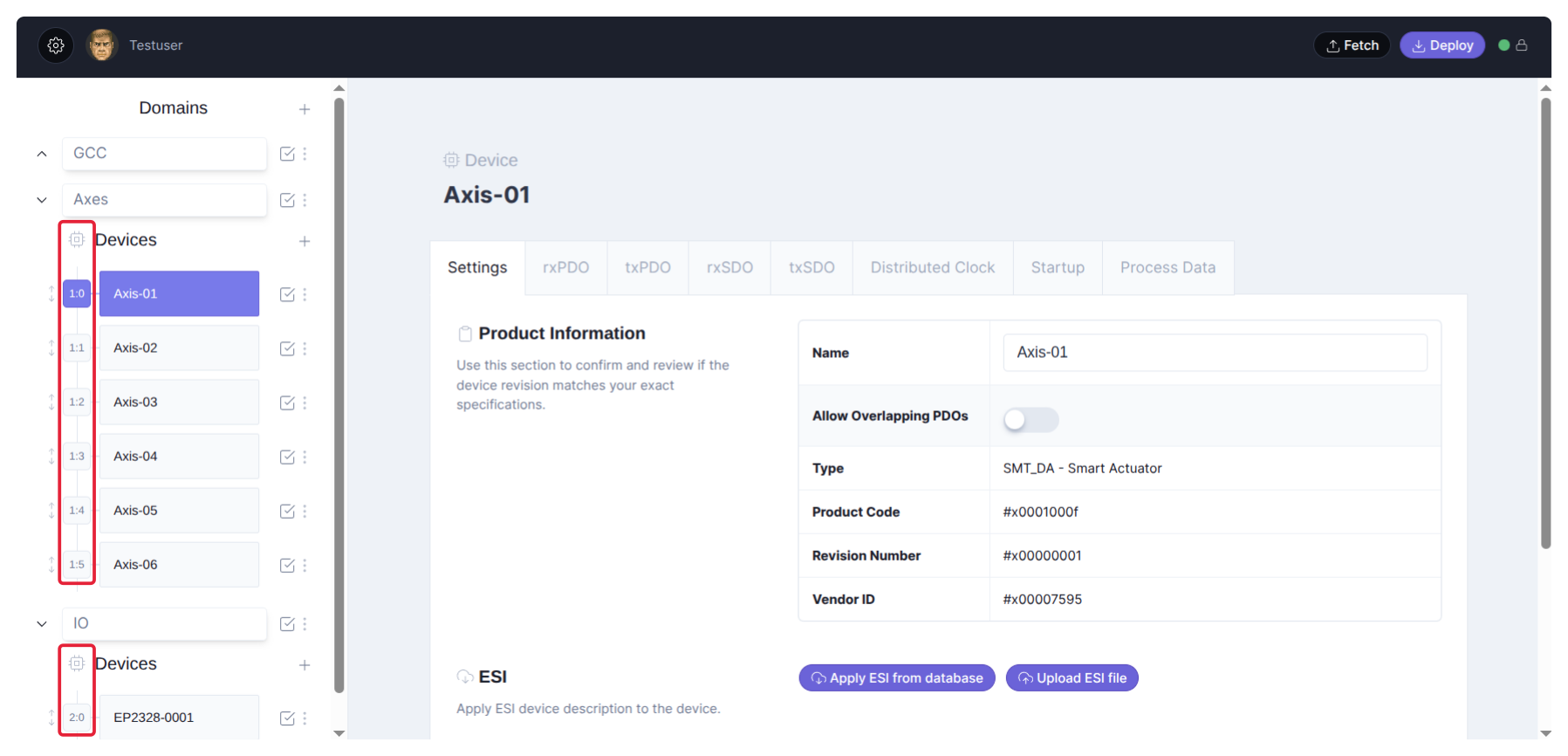
Add and configure a domain
- Press
(
Add Domain) next toDomainsto add a domain at the end. It is calledUntitleduntil you name it. The button appears once the configuration holds a device. - Click the domain to open its settings on the right, and set them:
| Setting | What it does | Default |
|---|---|---|
Name |
The name of the domain. | empty, shown as Untitled |
Frequency Divider |
Exchange the domain’s data every Nth cycle of the EtherCAT master. | 1 (every cycle) |
Simulation |
Simulate every device in the domain while the application runs in production mode. The domain then shows Simulation Mode in the panel. In simulation mode every domain is simulated anyway. |
off |
Apply ESI's from database to all devices in this domain |
Press Apply to complete every device in the domain from the ESI database of motorcortex.io, after you confirm. |
The menu of a domain (
, More Actions) has:
Add: a new domain right after this one,Clone: a copy called<name> (copy)with copies of all its devices, at new positions after the highest one in use,delete: remove the domain and its devices. Deleting the last domain leaves an emptyDefaultdomain.
The checkbox of a domain (
, Include in Ethercat Message) switches the domain and all its devices on or off at once.
Changes stay in the tool until you deploy the configuration.