Home
7 minute read
The HOME tab provides you with a control interface which gives tou the ability to axes manually or automatically. In this section will provide a explanation of all the functions in the HOME tab.
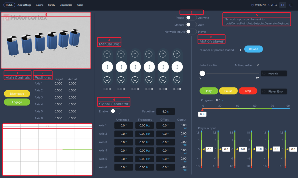
Main Controls [1]
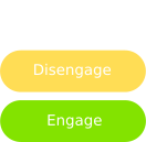
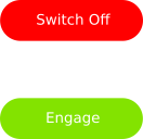
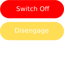
The Main Controls represent the state machine of the system. The states can be changed by pressing Disengage, Engage and Switch Off. After the system is powered on, it will automatically start in the OFF_S state. You can find the current system state in the top right corner.
To activate the system press Disengage button. The system will enter the DISENGAGE_S state Servo-drives will be powered but movement commands are not tracked.
From the DISENGAGE_S state you can go to the ENGAGE_S State by pressing the Engaged button. the system is activated!
In case of a E-stop error the system will recover in the OFF_S state.
Mode Switches [2]
If the system is in the ENGAGED_S there are a couple Mode options to control the servo-drive.


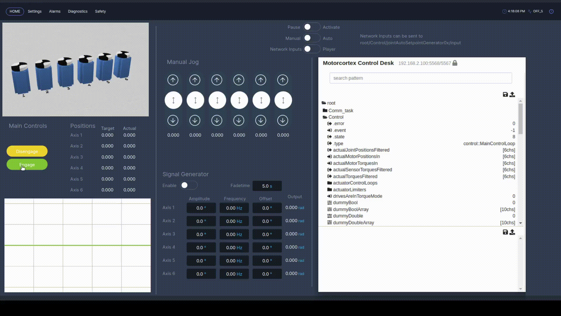
Manual Jog [3]
Manual Jog can be used in Manual mode and enables the you to jog each axis separately by means of the joystick.
In Engaged_S state and Active mode it is possible to use Manual Jog.
You can move each axis with a joystick:
- Moving up resulting in a clockwise rotational movement,
- Moving down resulting in a counter-clockwise rotational movement.
The Joysticks are aligned from left to right respectively axis 1 till 6. The current target position is displayed underneath each joystick.
In this example the system is put in Engaged_S state the modes are set to Active mode and Manual mode. The values of the Manual Jog outputs are changed by means of moving the joystick.

Signal Generator [4]
Signal Generator can be used in Manual mode and enables the user to control one or multiple axes by means of a Signal Generator.
Per Default a Sine signal is generated with the Signal Generator. This can be changed in Motorcortex Desk.
The Signal Generator can be configured by a set of parameters: Fadetime, Amplitude, Frequency and Offset for each axis. The output of the signal generator is displayed in the output column.


In this example the system is put in Engaged_S state the modes are set to Active mode and Manual mode. The signal parameters have been defined before the signal generator is enabled.

Network Inputs [5]
You can use Network Inputs to control Advanced Setpoint Generators with are adjustable in: Velocity, Acceleration and Jerk parameters. You can use Network Input if system is in Engaged_S and the mode switches are set to Active, Auto and Network Input.
While in Network Input mode, Using Motorcotex Desk you can parameterize the Setpoint Generator under the following path: root/Control/jointAutoSetpointGenerator0x/. In this path the following parameters can be adjusted:
input- This is the input of the Setpoint Generator [rad].maxAcc- Here you can adjust the maximum Acceleration [rad/s^2].maxJerk- Here you can define the maximum Jerk [rad/s^3].maxTarget- Here you can define the maximum Target Position [rad].MaxVel- Here you can define the maximum Velocity [rad/s].output- This is the output of the Setpoint Generator [rad].
In this example the system is put in Engaged_S state the modes are set to Active mode, Auto mode and Network Input mode. In the side frame you can see the Desk-tool. within the parameter tree under path root/Control/jointAutoSetpointGenerator0x the settings maxACC, maxJerk and maxVel of the SetPointGenerator need to have a value other than the default value of zero. after this you can define an input value.
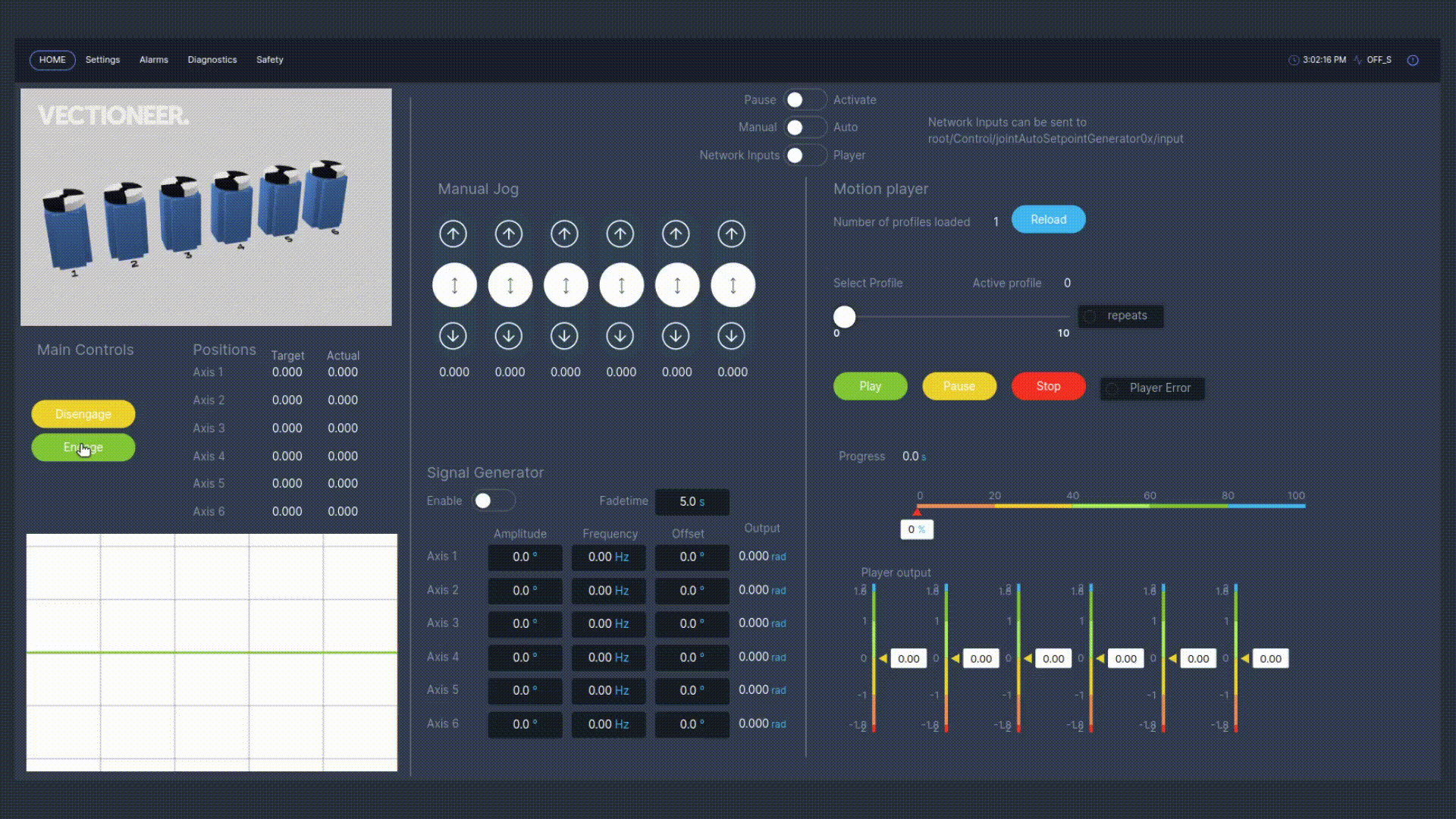
Motion Player [6]
The Motion Player is part of the auto mode and enables the user to play a motion-file, which is uploaded after defining its location in the configuration.json file.
With the motion player the user can define custom motion profiles defined in a .csv file. These files can be loaded to Motorcortex Generic App by storing the .csv file in a predefined default path as specified in the config.json: "MotionPlayer": "/etc/motorcortex/config/motionfiles/". You can change the motion file path in the config.json to you own liking.
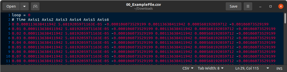
The motion file format should meet the following criteria in order for the motion player to read it. A example file is stored in /etc/motorcortex/config/motionfiles/00_ExampleFile.csv.
Motion file criteria:
- The motion file name should have the following format
xx_yyyy.csv.xxrepresents the motion file index number in the range of 00..99 as theyyyyvalue can be changed to every name you like. - The first row of the .csv format should have the value
loop = z.zrepresents the repeat function of the motion player, for no repeats replacezwith0. For the Motion Player to repeat automatically the motion file replacezwith1. - The second row of the .csv file contains column information
# Time Axis1 Axis2 Axis3 Axis4 Axis5 Axis6. - The data in each row is
separatedwith aspacerto indicate the columns. Note: all other spacing signs will result in motion player failure.
In this example the system is put in Engaged_S state the modes are set to Active mode, Auto mode and Player mode. The 00_ExampleFile.csv is loaded, Index Profile: 0 selected. Repeats light is off because in the .csv file loop = 0. Motion file starts after pressing Play. While in play the Progress [s] starts to count and output data is shown in player output.
Positions [7]
In Positions the Target and Actual position of each axes is displayed. The Target position is defined as the summation of the Manual Jog and Signal Generator value. Because it is a summation it gives the possibility to Manual Jog on top of the signal generator.
Mini Plot [8]
In the mini plot the Actual position value of each axis is plotted in a different color.
Virtual Twin [9]
A 3D visualization of 6 axes is used to displayed movement of each axis based on its Actual position.