Definitions
3 minute read
Units
The Motion Controller shall use SI units, such as Seconds (sec), Meter (m), Radian (rad), Newton (N), Newton * Meter (Nm), Kelvin (K), Kilogram (kg), Pascal (Pa). If other units are used, it shall be clear from the signal name that this is defined in another unit (e.g. time_ns for time in nanoseconds, or pressure_bar for pressures in Bar, or Temperature_C for temperatures in degree Celsius).
Frames
A Frame is as a representation of a position and an orientation of a body in space. The mathematical representation of a Frame is identical to that of a Pose. Frames will be used to define the origins of coordinate systems. All Frames are right-handed frames. Inertial frames are indicated by an I superscript (), moving frames are indicated by a superscript referencing the parent Frame () The system has the following pre-defined Frames:
- Inertial Reference Frame (); a fixed reference point attached to the world. Where the X-axis points forward, the Y-axis points right and the Z-axis points up. This also means that looking from the top down, positive rotation around the Z-axis is Counter Clockwise and positive rotation around the Y axis pitches down.
- Robot Base Frame (); The positive Z-axis coincides with the rotation axis of the second joint and points upwards.
- Robot Tool (or Endeffector) Frame (); this frame is attached to the last link of the robot at the center of the flange (where the tool will be attached). The positive Z-axis coincides with the rotation axis of the last joint and points away from the flange. The pose of this frame with respect to the Robot Base Frame is determined by the Pose of the robot .
Pose
A Pose is defined as a time varying combination of a linear position and an orientation of a Frame with respect to some reference (or Parent) Frame (see below). The Pose is a part of the system’s state. The robot pose can be described in two ways;
- as a set of Joint Coordinates or
- a set of three Cartesian coordinates (x,y,z) for the endeffector tip location in combination with a set of joint coordinates for the remaining axes. Note that the robot may or may not be able to reach a Cartesian Pose, and there may be multiple Joint POse solutions for the robot to reach the same Cartesian Pose. When calculating Inverse Kinematics this ambiguity is usually solved by picking the solution where the calculated Joint Coordinates are “closest” to some Reference Joint Coordinates; usually the previous Pose is used as the Reference.
Singularity Point
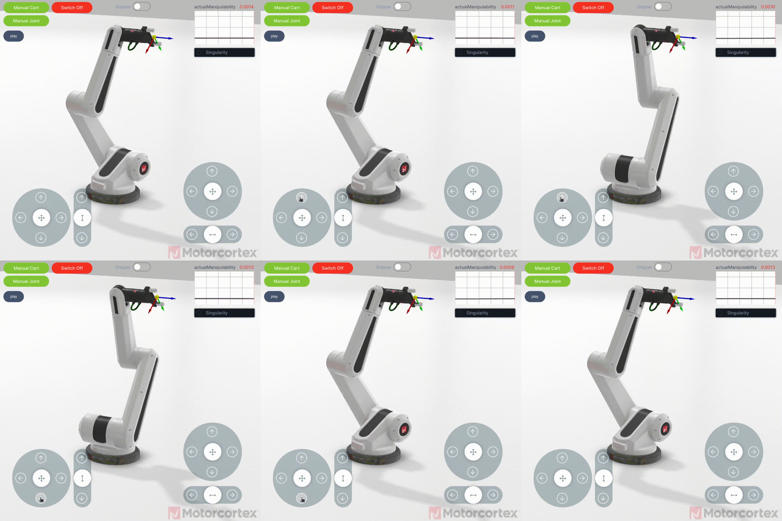
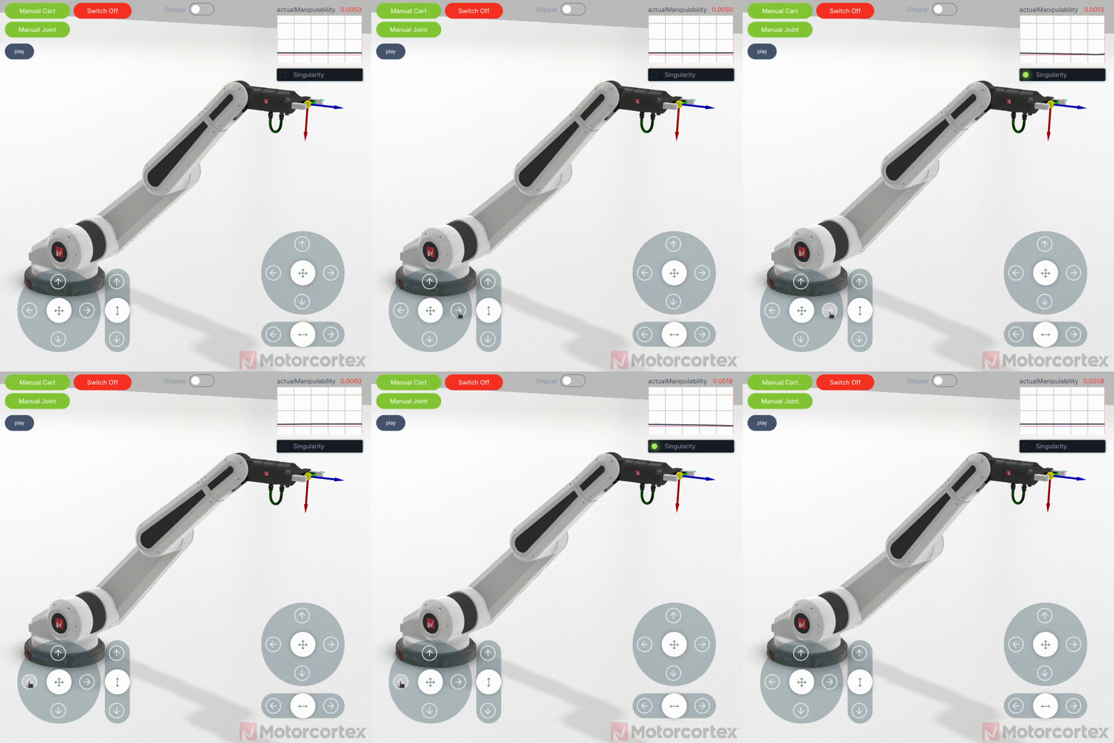
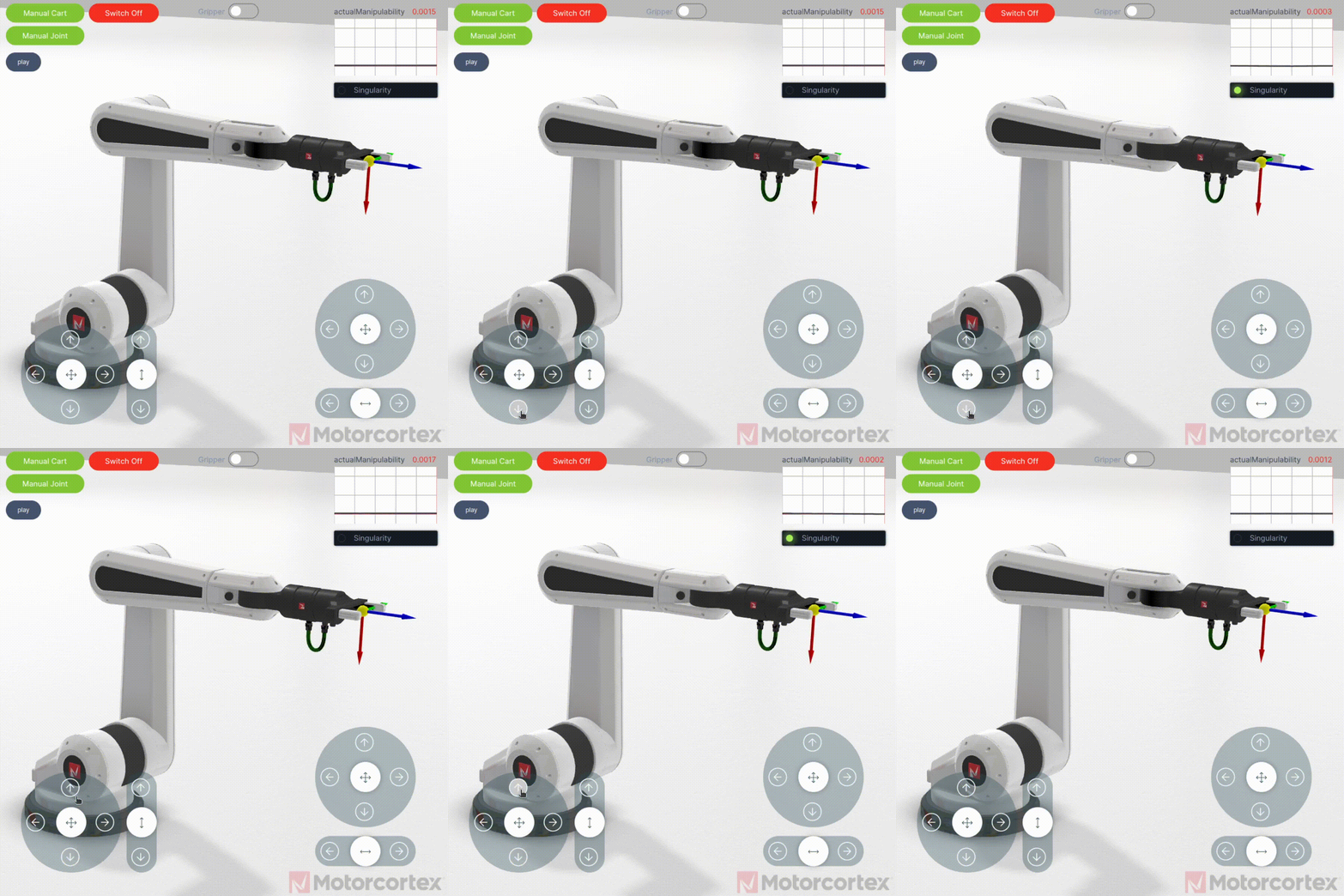
A robot near a singularity point can cause unpredictable robot motion. There are three type of singularities:
Note
Adjust the manipulability for your robot in such a way that you are unable to reach a singularity point.
1. Shoulder singularity
When the center of the robot’s wrist aligns with the axis of joint 1, it caused joint 1 and 4 try to spin 180 degrees.

2. Elbow singularity
When the center of the robot’s wrist lies on the same plan as joint 2 and 3, it causes joint 3 to lock or jump instantaneously

3. Wrist singularity
When two robot’s wrist axes (joint 4 and 6) line up with each other, cause the wrist to spin 180 degrees.
