Axis Settings
4 minute read
In the settings tab the user can parameterize and configure each axis. In this section you will learn how to configure your motor in the settings tab.
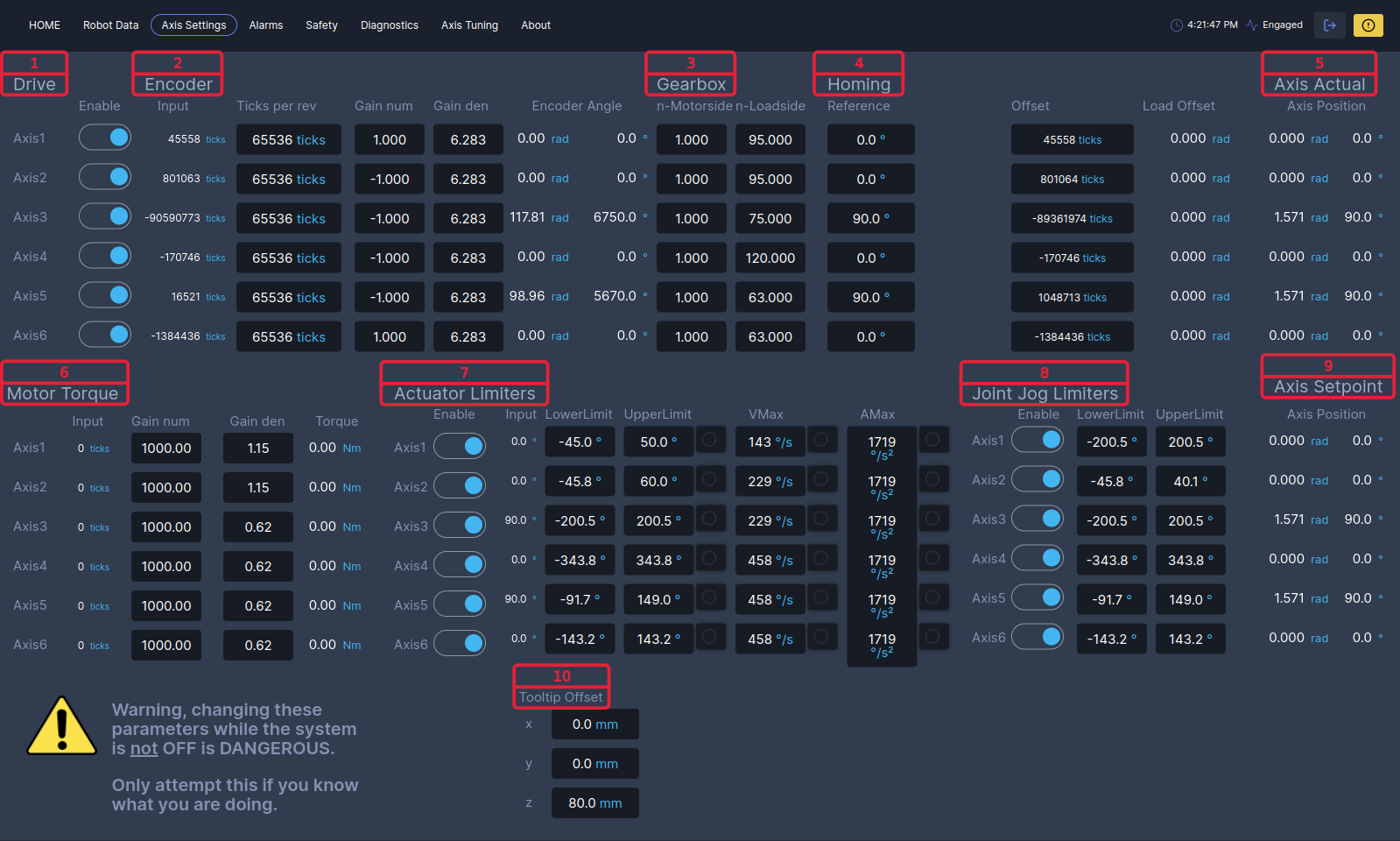
Under Drive you can enable or disable axes using the
enable switch. If an axis is enabled it can be controlled from the home tab. If an axis is disabled it will not be switched on and cannot be used. If axes are enabled but not physically present or not configured properly an error will be triggered.
Under Encoder you can set the encoder values for each axis, with the gain the value in ticks is transformed to radians, after it is transformed to degrees.
| Bar | Description |
|---|---|
Input |
The current encoder value in ticks. |
Ticks per rev |
Here you fill in the ticks per revolution of the encoder. |
Gain num |
Is the numerator of the gain. |
Gain den |
Is the denominator of the gain. |
Gain |
Is the ticks per rev times gain num/gain den. |
Encoder angle |
The gain times input is the current encoder angle in radians which is transformed to degrees. |
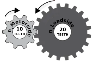
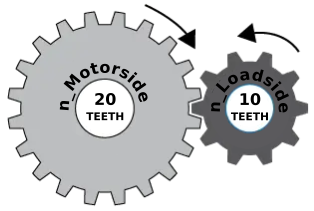
Set the gearbox according to the gear ratio specified by the manufacturer.
| Bar | Description |
|---|---|
Gear ratio |
n_Loadside / n_Motorside |
n-Motorside |
Number of teeth on Motorside. |
n-Loadside |
Number of teeth on Loadside. |
Under Homing you reference the axes, pressing Reference All will reference axes 1 till 6 at the same time. Axis settings are saved by pressing Save Settings.
| Bar | Description |
|---|---|
Reference |
In here you define your axis motor side reference angle [deg], pressing Reference will reference the axis. |
Offset |
The Offset is the difference in ticks between the encoder input and reference angle. |
Load Offset |
The Load Offset is offset on the load side. For example axis 3 and 5 have an offset of 90 degrees motor side. But have a virtual 0deg offset at the load side, knowing this you can set variable zero point of your axis. |
Under Axis Actual you can read out the actual axis position in radians and degrees.
Under the Motor Torque the Torque conversion can be configured.
| Bar | Description |
|---|---|
Input |
The current torque value in ticks. |
Gain num |
Is the numerator of the gain. |
Gain den |
Is the denominator of the gain. |
Gain |
The input motor torque value (in ticks) is multiplied by the gain to result in the Torque. |
Torque |
The Torque value in for example Nm. (You may also configure it to represent a Force in N, which is convenient for linear axes.) |
PVA limiters enables the user to turn on and off, set Position, Velocity and Acceleration limits to each axis individually. If a limiters is exceeded, the limit exceeded light
will turn on.
| Bar | Description |
|---|---|
Enable |
With the
enable switch you can enable or disable the PVA limiter per axis. |
Input |
The actual reference axis position in [degrees] . |
LowerLimit |
The LowerLimit is a position limiter, in here you can set the lower limit in [degrees]. |
UpperLimit |
The UpperLimit is a position limiter, in here you can set the upper limit in [degrees]. |
VMax |
The VMax you can set the velocity limiter, in here you can set the velocity in [deg/s]. |
AMax |
The AMax you can set the acceleration limiter, in here you can set the acceleration in [deg/s^2]. |
Under Joint Jog Limiters you can set the maximum position jog of each joint.
| Bar | Description |
|---|---|
Enable |
With the
enable switch you can enable or disable the joint jog limiter per axis. |
LowerLimit |
The LowerLimit is a jog limiter, in here you can set the lower limit in [degrees]. |
UpperLimit |
The UpperLimit is a jog limiter, in here you can set the upper limit in [degrees]. |
Under Axis Setpoint you can read out the set axis position in radians and degrees.
Under Tooltip Offset you can specify the tooltip offset in [mm] for x , y and z direction.