Device Configuration Panel
15 minute read
Device Configuration Panel
In the middle of the Motorcortex-ECAT screen you will find the Device Configuration Panel. With this panel you can configure your devices. A Device Configuration Panel has multiple tabs:
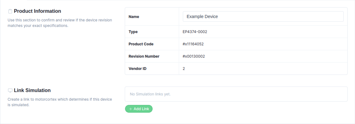
In the Settings tab, the device product information is listed. It enables changing the device Name, applying an ESI file, and defining a simulation link
-
In the
Namefield, enter a new Device Name (for example, SMT_DA - Smart Actuator). If multiple devices share the same name, the device appears red in the Domain Configuration Panel. It is recommended to assign each device a unique name. -
Enable
Allow Overlapping PDOsif the configured devicesupports overlapping PDOs. Be aware that using this option on an unsupported device may cause data corruption or communication errors. -
Displays EtherCAT slave information, such as Type, Product Code, Revision Number, and Vendor ID.
-
By pressing the
Apply ESI from databasebutton, the software checks if the device’sRevision Number and Product Codematch an ESI file stored in theESI-database, applying it if found. If the device is not in the ESI-database, an ESI file can beapplied manuallyby pressing theUpload ESI filebutton.
Device Simulation Settings
When the system is running in Production mode and you want to simulate a domain that contains EtherCAT drives, you must generate a separate simulation link for each EtherCAT drive that is part of the simulation domain.
-
Define a Simulation Link. Press
Add Linkto add a simulation link to the device.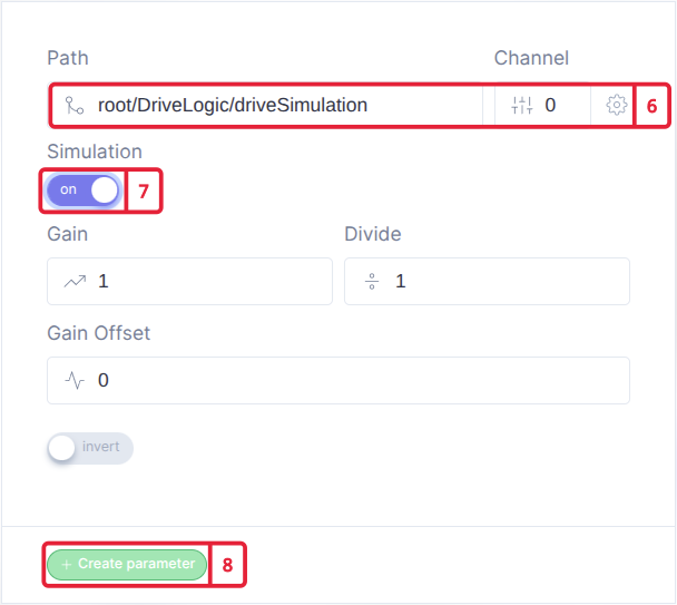
-
Add the simulation link that matches your EtherCAT drive. Use the prefix
root/DriveLogic/driveSimulation, and assignchannel 0fordrive 1; increase the channel for each additional drive. -
Enable the Simulation Flag.
-
Press the
Create parameterbutton to add the simulation linking.
rxPDOs are used to transfer data cyclically between the EtherCAT master and the EtherCAT slave. Typical examples of data mapped to rxPDOs are entries such as target positions, velocities, and control words.
You can create mapping in two methods, either manually starting with an empty mapping, or from an ESI-file.
Add New PDO mapping:
You can add manually a PDO mapping with custom entries. Be aware, when creating a custom mapping, that your slave also needs to supports this. It is highly recommended to use and ESI-file instead of manual mapping.

- Add a new
rxPDOby pressing theAdd PDObutton. This adds a new PDO mapping input field.

-
At
0000, you need to define theObject Idinhex. (Example: 1600) -
At
Group, define theGroup Namefor this PDO mapping. All entries inside this PDO are stored in this group and are visible via the desk-tool. -
At
Name, define aName(Example:.data). This name will be displayed in the parameter tree (desk-tool). The.dataobject will contain all information of the PDO mapping, and can be copied to another PDO mapping via linking. -
Define the
syncmanagerused for this PDO mapping. -
Use the
Include in EtherCAT messagecheckbox to include or exclude the PDO from the EtherCAT message. Excluded PDOs are not configured inside the EtherCAT device. -
Use the
Show in data treebutton to choose whether to hide or show this PDO inside the parameter tree (desk-tool). -
Press the
More Actionsbutton to open adropdown list:-
With the
add a link.dataobject from one PDO mapping to another. Be aware that the the size of the copied data should be the same as the PDO mapping size. -
With the
Deletebutton, you can delete an entry from the list.
-
Add New Entry:
Example:
| Name: | Index:Sub: | Type: | Bit Size: |
|---|---|---|---|
| Control Word | 0x6040:00 | UINT | 16 |
-
At
- 0000:00, you need to define theObject IndexandSubindex. (Example: 6040:00) -
At
Group, define theGroup Namefor this entry mapping. All entries with the same group name are stored in the same group and are visible via the desk-tool. -
At
Name, define aName(Example: Control Word). This name will be displayed in the parameter tree (desk-tool). -
Define the data
sizeandtype(Example: UINT16). If a data type is not filled in, the input field appears red. -
Use the
Include in EtherCAT messagecheckbox to include or exclude the entry from the EtherCAT message. Excluded entries are not configured inside the EtherCAT device. -
Use the
Show in data treebutton to choose whether to hide or show this entry inside the parameter tree (desk-tool). -
Press the
More Actionsbutton to open adropdown list:-
With the
add a link(Motorcortex parameter) to the mapped entry. Information from this link is copied to this entry mapping. -
With the
Add Mappingbutton you can subdivide the entry into bits; the mapping is displayed as a decimal number. -
With the
Deletebutton, you can delete an entry from the list.
-
txPDOs are used to transfer data cyclically between EtherCAT master and the EtherCAT slave. Typical examples of data mapped to txPDOs are entries such as actual positions, velocities, and status words.
You can create mapping in two methods, either manually starting with an empty mapping, or from an ESI-file.
Add New PDO mapping:
You can add manually a PDO mapping with custom entries. Be aware, when creating a custom mapping, that your slave also needs to supports this. It is highly recommended to use and ESI-file instead of manual mapping.
- Add a new
txPDOby pressing theAdd PDObutton. This adds a new PDO mapping input field.
-
At
0000, you need to define theObject Idinhex. (Example: 1A00) -
At
Group, define theGroup Namefor this PDO mapping. All entries inside this PDO are stored in this group and are visible via the desk-tool. -
At
Name, define aName(Example:.data). This name will be displayed in the parameter tree (desk-tool). The.dataobject will contain all information of the PDO mapping, and can be copied to another PDO mapping via linking. -
Define the
syncmanagerused for this PDO mapping. -
Use the
Include in EtherCAT messagecheckbox to include or exclude the PDO from the EtherCAT message. Excluded PDOs are not configured inside the EtherCAT device. -
Use the
Show in data treebutton to choose whether to hide or show this PDO inside the parameter tree (desk-tool). -
Press the
More Actionsbutton to open adropdown list:-
With the
add a link.dataobject from one PDO mapping to another. Be aware that the the size of the copied data should be the same as the PDO mapping size. -
With the
Deletebutton, you can delete an entry from the list.
-
Add New Entry:
Example:
| Name: | Index:Sub: | Type: | Bit Size: |
|---|---|---|---|
| Status Word | 0x6041:00 | UINT | 16 |
-
At
- 0000:00, you need to define theObject IndexandSubindex. (Example: 6041:00) -
At
Group, define theGroup Namefor this entry mapping. All entries with the same group name are stored in the same group and are visible via the desk-tool. -
At
Name, define aName(Example: Status Word). This name will be displayed in the parameter tree (desk-tool). -
Define the data
sizeandtype(Example: UINT16). If a data type is not filled in, the input field appears red. -
Use the
Include in EtherCAT messagecheckbox to include or exclude the entry from the EtherCAT message. Excluded entries are not configured inside the EtherCAT device. -
Use the
Show in data treebutton to choose whether to hide or show this entry inside the parameter tree (desk-tool). -
Press the
More Actionsbutton to open adropdown list:-
With the
add a link(Motorcortex parameter) to the mapped entry. Information from this link is copied to this entry mapping. -
With the
Add Mappingbutton you can subdivide the entry into bits; the mapping is displayed as a decimal number. -
With the
Deletebutton, you can delete an entry from the list.
-

rxSDOs are used to transfer data on request between the EtherCAT master and EtherCAT slave.
Add New SDO mapping:
- Pressing the
Add SDObutton, adds a new SDO mapping input field which can be configured.
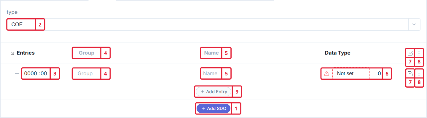
- At
Type, define the EtherCAT protocols either CoE (CAN over EtherCAT) or SoE (Sercos over EtherCAT)
Add rxSDO Example:
| Name: | Index:Sub: | Type: | Bit Size: |
|---|---|---|---|
| Position loop Kp | 0x2012:01 | Float | 32 |
| Store all parameters | 0x1010:01 | UInt | 32 |
-
At
- 0000:00, you need to define theObject IndexandSubindexinhex. (Example: 2012:01) -
At
Group, define theGroup Namefor this SDO mapping. All entries inside this SDO are stored in this group and are visible via the desk-tool. -
At
Name, define aNameto the entry (Example:Position loop Kp). This name will be displayed in the parameter tree (desk-tool). It is also possible to add a name to the SDO, this will display the overall SDO data. -
Define the data
sizeandtype(Example: Float 32). If a data type is not filled in, the input field appears red. -
Use the
Include in EtherCAT messagecheckbox to include or exclude the SDO from the EtherCAT message. Excluded SDOs are not configured inside the EtherCAT device. -
Press the
More Actionsbutton to open adropdown list:-
With the
add a linkto the SDO entry. -
With the
Deletebutton, you can delete an SDO entry from the list.
-
-
Pressing the
Add Entrybutton, adds a new entry to the SDO.
txSDOs are used to transfer data on request between the EtherCAT master and EtherCAT slave.
Add New SDO mapping:
- Pressing the
Add SDObutton, adds a new SDO mapping input field which can be configured.
- At
Type, define the EtherCAT protocols either CoE (CAN over EtherCAT) or SoE (Sercos over EtherCAT)
Add txSDO Example:
| Name: | Index:Sub: | Type: | Bit Size: |
|---|---|---|---|
| Error Code | 0x603F:00 | UInt | 16 |
| Error Report | 0x203F:01 | String | 8 |
-
At
- 0000:00, you need to define theObject IndexandSubindexinhex. (Example: 603F:00) -
At
Group, define theGroup Namefor this SDO mapping. All entries inside this SDO are stored in this group and are visible via the desk-tool. -
At
Name, define aNameto the entry (Example:Error Code). This name will be displayed in the parameter tree (desk-tool). It is also possible to add a name to the SDO, this will display the overall SDO data. -
Define the data
sizeandtype(Example: UInt). If a data type is not filled in, the input field appears red. -
Use the
Include in EtherCAT messagecheckbox to include or exclude the SDO from the EtherCAT message. Excluded SDOs are not configured inside the EtherCAT device. -
Press the
More Actionsbutton to open adropdown list:-
With the
add a linkto the SDO entry. -
With the
Deletebutton, you can delete an SDO entry from the list.
-
-
Pressing the
Add Entrybutton, adds a new entry to the SDO.
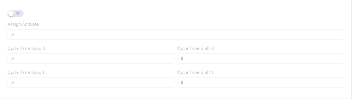
Distributed clock settings are used to synchronize all devices on the network to a unified system time.
-
Enables the DC clock for the device.
-
If an ESI file is applied, the Select from preset dropdown displays the available options. Select one of the available DC clock settings.
-
Enter the
hexvalue of the preferredAssign Activate. Using Select from preset automatically applies the correct Assign Activate value based on the chosen preset. -
For
Mode, you can select eitherCycleorUser Defined. -
Based on the selected
Mode:- For
Cycle, you need to define aFactorfor Cycle Time Sync/Shift 0. If the factor ispositive: Fieldbus Task Cycle Time * Factor. If the factor isnegative: Fieldbus Task Cycle Time / Factor. For Cycle Time Shift 0, the default factor of -2 can be used. - For
User Defined, you need to specify the Cycle Time Sync/Shift 0 value in nanoseconds [ns]. For example, if the field bus task is configured to 1 kHz:- cycle_time_sync0 [ns] = field bus task cycle time [ns] = 1,000,000 ns
- cycle_time_shift0 [ns] = 50% of the field bus task cycle time [ns] = 500,000 ns
- For
Note
DC clock settings are specified in the ESI file under the name Assign Activate.
Related Information:
A startup list is loaded each time the device power cycles, it parametrizes your device with the set of configured parameters
-
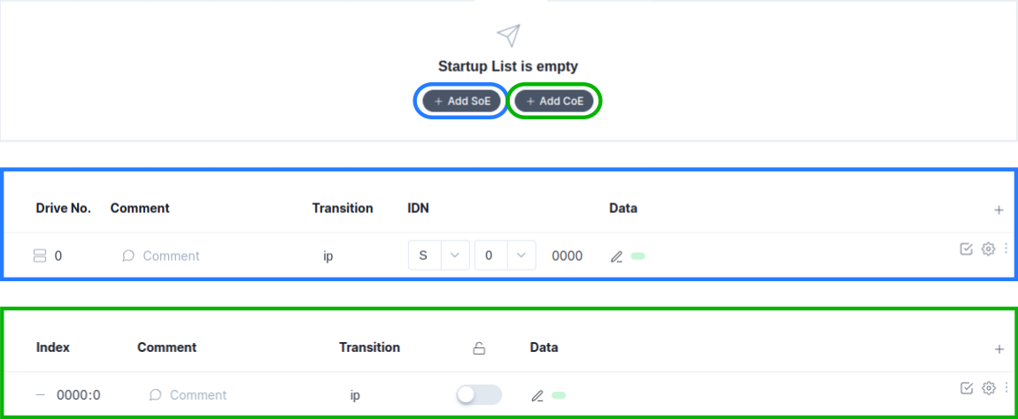
In the main screen of the
startup tab, you can add startup parameters forCoE,SoEandEoE. Either manually or via uploading a startup parameter list. -
Pressing the Upload button, opens a tab in which you can upload a startup.xml parameter file for example:
<?xml version="1.0" encoding="ISO-8859-1"?>
<EtherCATMailbox>
    <CoE>
<!-- Input Type Analog Input 01-->
        <InitCmds>
            <InitCmd>
                <Transition>PS</Transition>
                <Comment><![CDATA[Input Type]]></Comment>
                <Timeout>0</Timeout>
                <Ccs>1</Ccs>
                <Index>63488</Index>
                <SubIndex>01</SubIndex>
                <Data>0000</Data> <!-- -10..+10V -->
                <!--<Data>0100</Data> --> <!-- 0..+20mA -->
                <!--<Data>0200</Data> --> <!-- 4..+20mA -->
                <!--<Data>0300</Data> --> <!-- 0..+10V -->
            </InitCmd>
        </InitCmds>
    </CoE>
</EtherCATMailbox>
<?xml version="1.0" encoding="utf-8"?>
<EtherCATMailbox>
  <SoE>
    <InitCmds>
      <InitCmd>
        <Transition>PS</Transition>
        <Comment><![CDATA[Telegram type]]></Comment>
        <Timeout>0</Timeout>
        <OpCode>3</OpCode>
        <DriveNo>0</DriveNo>
        <IDN>15</IDN>
        <Elements>64</Elements>
        <Attribute>0</Attribute>
        <Data>0700</Data>
      </InitCmd>
    </InitCmds>
  </SoE>
</EtherCATMailbox>
<?xml version="1.0" encoding="ISO-8859-1"?>
<EtherCATMailbox>
  <EoE>
    <InitCmds>
      <InitCmd Fixed="true">
        <Transition>IP</Transition>
        <Transition>PS</Transition>
        <Comment><![CDATA[eoe init]]></Comment>
        <Timeout>0</Timeout>
        <Data>020000000f0000000201051003e97b02000a00ffffff0102000a000000000000000000000000000000000000000000000000000000000000000000000000</Data>
        <!-- 02000000 --> <!-- Header[4] -->
        <!-- 0f000000 --> <!-- Flags[4] -->
        <!-- 0201051003e9 --> <!-- MAC Address[6] is 02:01:05:10:03:e9 -->
        <!-- 7b02000a --> <!-- Ip Address[4] is 10.0.2.123 -->
        <!-- 00ffffff --> <!-- Subent Mark[4] is 255.255.255.0  -->
        <!-- 0102000a --> <!-- Gateway[4] is 10.0.2.1-->
        <!-- 00000000 --> <!-- Dns Server[4] -->
        <!-- 0000000000000000000000000000000000000000000000000000000000000000 --> <!-- Dns Name[32] -->
      </InitCmd>
    </InitCmds>
  </EoE>
</EtherCATMailbox>
<?xml version="1.0" encoding="ISO-8859-1"?>
<EtherCATMailbox>
    <CoE>
<!-- Input Type Analog Input 01-->
        <InitCmds>
            <InitCmd>
                <Transition>PS</Transition>
                <Comment><![CDATA[Input Type]]></Comment>
                <Timeout>0</Timeout>
                <Ccs>1</Ccs>
                <Index>63488</Index>
                <SubIndex>01</SubIndex>
                <Data>0000</Data> <!-- -10..+10V -->
                <!--<Data>0100</Data> --> <!-- 0..+20mA -->
                <!--<Data>0200</Data> --> <!-- 4..+20mA -->
                <!--<Data>0300</Data> --> <!-- 0..+10V -->
            </InitCmd>
        </InitCmds>
    </CoE>
    <EoE>
        <InitCmds>
            <InitCmd Fixed="true">
                <Transition>IP</Transition>
                <Transition>PS</Transition>
                <Comment><![CDATA[eoe init]]></Comment>
                <Timeout>0</Timeout>
                <Data>020000000f0000000201051003e97b02000a00ffffff0102000a000000000000000000000000000000000000000000000000000000000000000000000000</Data>
                <!-- 02000000 --> <!-- Header[4] -->
                <!-- 0f000000 --> <!-- Flags[4] -->
                <!-- 0201051003e9 --> <!-- MAC Address[6] is 02:01:05:10:03:e9 -->
                <!-- 7b02000a --> <!-- Ip Address[4] is 10.0.2.123 -->
                <!-- 00ffffff --> <!-- Subent Mark[4] is 255.255.255.0  -->
                <!-- 0102000a --> <!-- Gateway[4] is 10.0.2.1-->
                <!-- 00000000 --> <!-- Dns Server[4] -->
                <!-- 0000000000000000000000000000000000000000000000000000000000000000 --> <!-- Dns Name[32] -->
            </InitCmd>
        </InitCmds>
    </EoE>
</EtherCATMailbox>
- Pressing the
Add Item, adds a manual configuration field.
Manual Configuration of CoE Startup Parameters

-
At
- 0000:00, you need to define theObject IndexandSubindexinhex(Example:F800:01). -
At
Comment, define acommentfor example the name of the entry (Example:Input Type). -
At
Data, you need to configure the parameter used at startup. -
You can enable
Complete Accessto transfer all sub-indices in one data packet to the EtherCAT slave. -
With
include in EtherCAT message, you can either include or exclude the configured entry from the startup list. For more option you can press :- The
Add Itembutton, adds a new entry to the startup list. - The
Deletebutton, removes the entry from the startup list.
- The
Manual Configuration of SoE Startup Parameters

-
At
Drive No., you need to define the drive number. For single-axis devices, the drive number is typically 0. For multi-axis drives, each axis or motor controller is addressed by its specific index (e.g., drive 0, drive 1, etc.) -
At
Transition, you define between which transition state the parameter is applied. -
At
Comment, define acommentfor example the name of the entry. -
At
Data, you need to configure the parameter used at startup. -
For IDN you fill in the IDN number: S-x-yyyy/P-x-yyyy.
"S"for Standard data,"P"for Product-specific data.xparameter set usually from 0 to 7 and.yyyyData-block number usually from 0 to 4095.
-
With
include in EtherCAT message, you can either include or exclude the configured entry from the startup list. For more option you can press :- The
Add Itembutton, adds a new entry to the startup list. - The
Deletebutton, removes the entry from the startup list.
- The
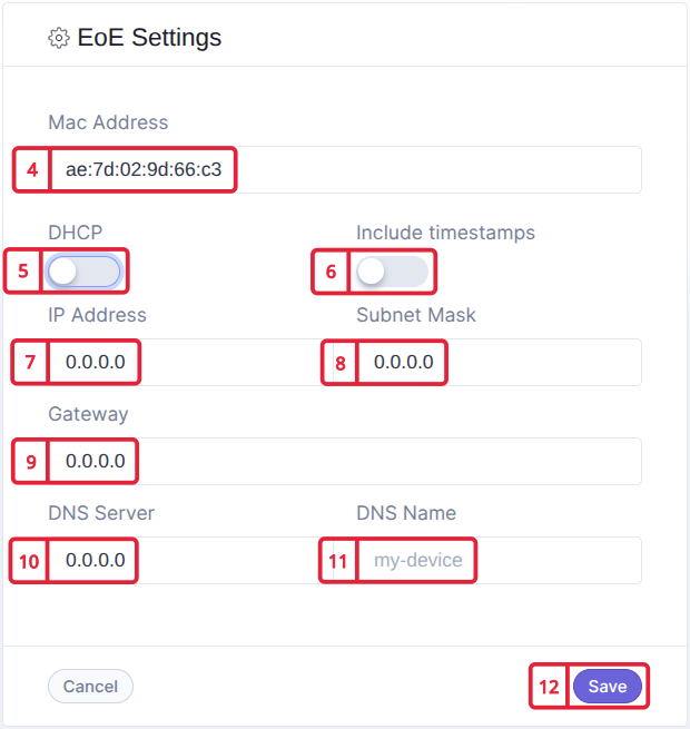
Manual Configuration of EoE Startup Parameters

-
At
Comment, define acommentfor example the name of the entry (example:eoe init). -
At
Date: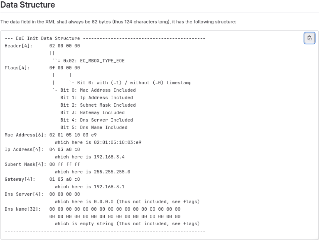
-
With
include in EtherCAT message, you can either include or exclude the configured entry from the startup list. For more option you can press :- The
Add Itembutton, adds a new entry to the startup list. - The
Deletebutton, removes the entry from the startup list.
Pressing on , opens a visual editor, to configure EoE.
- The
-
Fill in the device MAC address.
-
Use to enable or disable DHCP.
-
Use to include or exclude timestamp to EoE package data.
-
Fill in the device IP Address.
-
Fill in the Subnet Mask.
-
Fill in the Gateway.
-
Fill in the DNS Server Address.
-
Fill in the DNS Name.
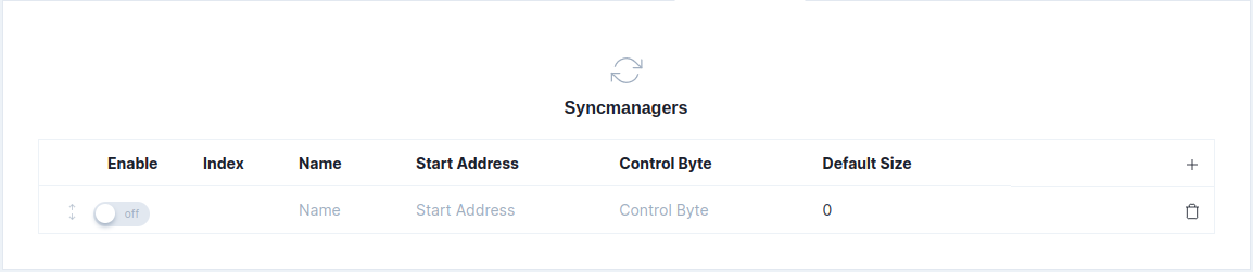
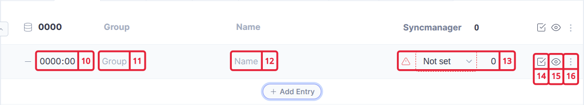
In the Process Data tab you can add, remove and enable Syncmanagers.
| Field | Description |
|---|---|
With this button you can Add Syncmanagers. |
|
| Enable | With the off switch you can include/exclude the syncmanager. |
| Index | Here you can number the syncmanagers. |
| Name | Here you can define a name for the syncmanager. |
| Start Address | In here you fill in the Hex number representation of the Start Address. |
| Control Byte | In here you fill in the Hex number representation of the Control Byte. |
| Default Size | In here you define the default size. |
With this button you can Delete Syncmanager. |