Postion Transformation
4 minute read
After linking the drive’s Target Position and Position Actual Value to Motorcortex parameters via ECAT-Tool, a conversion gain is essential for accurate unit conversion. This process ensures proper communication and control between the drive and Motorcortex.
Configure position transformation via the GUI
You can define the position transformation between the drive unit [ticks per revolution] and the Motorcortex unit [rad] through the GUI under the Axis Settings Tab.
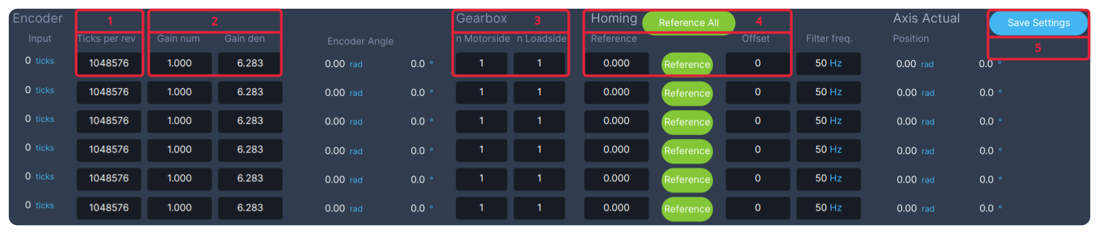
Example conversion between ticks and radians:
-
Set Encoder Resolution:
- In the
Ticks per revfield, enter the encoder resolution - Example: For a
20-bitencoder, enter1048576
- In the
-
Define Unit Conversion and Direction:
- Set the conversion from
per revolutiontoradians - Use the ratio:
Gain Num/Gain Den=1/2π - This ensures proper conversion between drive ticks and radians
- Configure the axis rotation direction using
Manual Jog, if the 3D visualization movesoppositeto the robot, setGain Num to -1
- Set the conversion from
-
Specify Gear Ratio (if applicable):
- If the gear ratio is not applied inside the drive, you must specify it here
- Example for an 80:1 gear ratio:
- Set nMotorside = 1
- Set nLoadside = 80
- If no external gear ratio, leave as 1:1
-
Set Reference Position (Production Mode): This step aligns the GUI’s 3D visualization with the real robot:
- Move the axis to a known reference angle (e.g., “Straight Up 0 deg”)
- Press reference to apply this position
- Or Enter Known Angles
- Fill in the current reference angles in [degrees] for each axis
- Press reference to apply these angles
- The offset in Ticks will be automatically stored in the Offset field
- Verify that the 3D visualization now matches the real robot’s position
- Move the axis to a known reference angle (e.g., “Straight Up 0 deg”)
-
Save Configuration
- Press Save Settings to store all your changes.
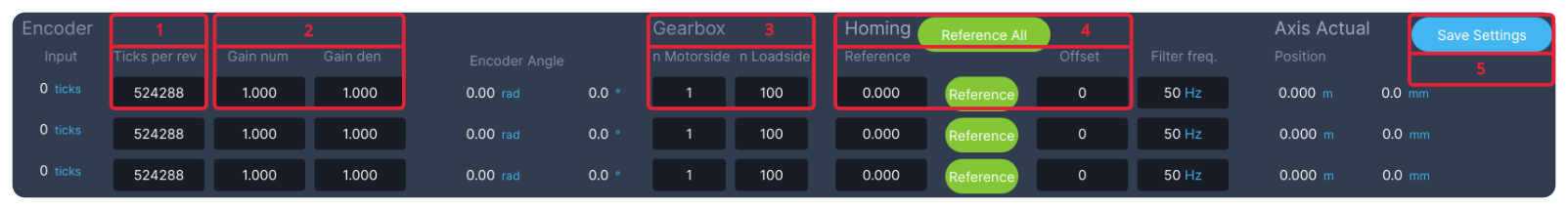
Example conversion between ticks and meters:
-
Set Encoder Resolution:
- In the
Ticks per revfield, enter the encoder resolution - Example: For a
19-bitencoder, enter524288
- In the
-
Define Direction:
- Use the ratio:
Gain Num/Gain Den=1/1 - Configure the axis movement direction using
Manual Jog, if the 3D visualization movesoppositeto the robot, setGain Num to -1
- Use the ratio:
-
Specify Gear Ratio and Meter Per Revolution conversion:
- If the gear ratio is not applied inside the drive, you must specify it here
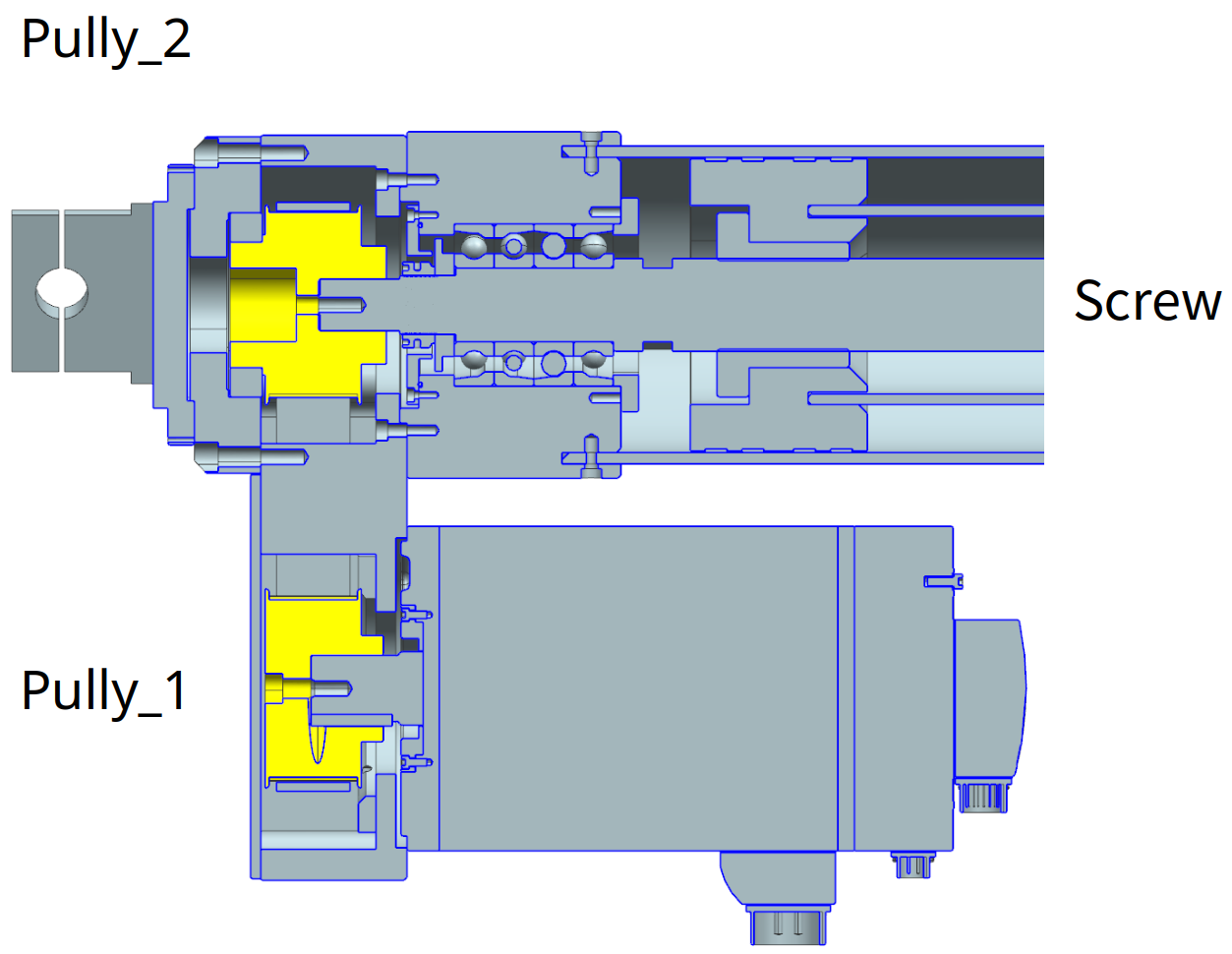
- Example for an 1:1 gear ratio betweem pully1 and pully2. pully2 drives a spindel with a 10mm pitch.
- Set nMotorside = 1
- Set nLoadside = 100
-
Set Reference Position (Production Mode): This step aligns the GUI’s 3D visualization with the real robot:
- Move the axis to a known reference angle (e.g., “0 meter”)
- Press reference to apply this position
- Or Enter Known Positions
- Fill in the current reference position in [meters] for each axis
- Press reference to apply this position
- The offset in Ticks will be automatically stored in the offset field
- Verify that the 3D visualization now matches the real robot’s position
- Move the axis to a known reference angle (e.g., “0 meter”)
-
Save Configuration
- Press Save Settings to store all your changes.
Example Setup:
Configure position transformation via the DESK-Tool
To configure position transformation for an axis (e.g., axis 1) using the desk-tool:
| GUI parameter: | Description: | Desk Parameter: |
|---|---|---|
| Encoder | ||
| Input | Actual encoder ticks | root/AxesControl/actuatorControlLoops/actuatorControlLoop01/positionTransformation/transducer/inputHardwareSide |
| Ticks per rev | Encoder resolution | root/AxesControl/actuatorControlLoops/actuatorControlLoop01/positionTransformation/transducer/ticksPerRevolution |
| Gain num | Numerator | root/AxesControl/actuatorControlLoops/actuatorControlLoop01/positionTransformation/transducer/gainNum |
| Gain den | Denominator | root/AxesControl/actuatorControlLoops/actuatorControlLoop01/positionTransformation/transducer/gainDen |
| Gearbox | ||
| n Motorside | gearboxMotorside | root/AxesControl/actuatorControlLoops/actuatorControlLoop01/gearboxMotorSide |
| n Loadside | gearboxLoadSide | root/AxesControl/actuatorControlLoops/actuatorControlLoop01/gearboxLoadSide |
| Homing | ||
| Reference | Reference angle in radians or position in meters | root/AxesControl/actuatorControlLoops/actuatorControlLoop01/positionTransformation/referencePositionLoadSide |
| Offset | Reference offset in ticks | root/AxesControl/actuatorControlLoops/actuatorControlLoop01/positionTransformation/transducer/offset |
| Axis Actual | ||
| Position | Axes position actual value in radians or meters | root/AxesControl/axesPositionsActual |
Configuring Persistence for Multiturn Position Storage
Persistence allows single-turn encoders to be used in multiturn applications by automatically storing current encoder ticks in persistence.bin. This feature is particularly useful for maintaining position information across power cycles.
To configure persistence for an axis (e.g., axis 1) using the desk-tool:
-
Enable persistance data:
- Set
root/AxesControl/actuatorControlLoops/actuatorControlLoop01/positionTransformation/transducer/enablePersistenceto1
- Set
-
Set maximum deviation tolerance after power cycles:
- Configure
root/AxesControl/actuatorControlLoops/actuatorControlLoop01/positionTransformation/transducer/deltaTicksMaxto your preferred value in[ticks]
- Configure
-
Monitor position difference:
- Check
root/AxesControl/actuatorControlLoops/actuatorControlLoop01/positionTransformation/transducer/deltaTicks, which shows the difference between current and stored position after power cycle
- Check
-
Error handling:
- If
deltaTicksexceedsdeltaTicksMax, the system will generate anES_Not_Referencederror - This error is resolved after referencing the axis
- If