Settings
2 minute read
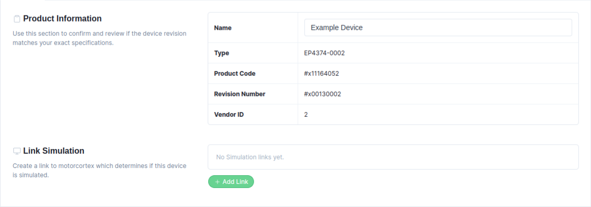
In the Settings tab, the device product information is listed. It enables changing the device Name, applying an ESI file, and defining a simulation link
-
In the
Namefield, enter a new Device Name (for example, SMT_DA - Smart Actuator). If multiple devices share the same name, the device appears red in the Domain Configuration Panel. It is recommended to assign each device a unique name. -
Enable
Allow Overlapping PDOsif the configured devicesupports overlapping PDOs. Be aware that using this option on an unsupported device may cause data corruption or communication errors. -
Displays EtherCAT slave information, such as Type, Product Code, Revision Number, and Vendor ID.
-
By pressing the
Apply ESI from databasebutton, the software checks if the device’sRevision Number and Product Codematch an ESI file stored in theESI-database, applying it if found. If the device is not in the ESI-database, an ESI file can beapplied manuallyby pressing theUpload ESI filebutton.
Device Simulation Settings
When the system is running in Production mode and you want to simulate a domain that contains EtherCAT drives, you must generate a separate simulation link for each EtherCAT drive that is part of the simulation domain.
-
Define a Simulation Link. Press
Add Linkto add a simulation link to the device.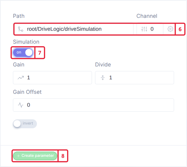
-
Add the simulation link that matches your EtherCAT drive. Use the prefix
root/DriveLogic/driveSimulation, and assignchannel 0fordrive 1; increase the channel for each additional drive. -
Enable the Simulation Flag.
-
Press the
Create parameterbutton to add the simulation linking.