mech
5 minute read
/etc/motorcortex/config/
└── mech
    └── mech-parameter.xml
mech-parameter.xml
A kinematic model is a mathematical description of the robot, expressed in the mech-parameters.xml containing:
- Robot name (robot name=“myRobot”)
- Degrees of Freedom (numberDoFs=“nNumber”)
- IK solver type (type=“mySolverType”)
- Basepose
- Segments
Note
Controlling your robot in cartesian space, requires a correct mech-parameter.xml
Warning
When applying changed to the mech-parameter.xml it is strongly recommended to test your application in Simulation mode. An incorrect configured mech-parameter.xml can lead to set point jumps.
Degrees of freedom
Defined as numberDoFs="nNumber" for nNumber fill in the degrees of freedom of your robot.
IK solver types
Define the required solver type for your robot in "mySolverType". Depended on the solver type the mech-parameter file can either have .xml or .json format:
.xml format types:
- anthropomorphic This analytic solver is suitable for 6DOF robots with a spherical wrist; the last three axes intersect at a single point. This type of robot is also known as a Puma-type robot.
- anthropomorphic2 This analytic solver is suitable for 6DOF robots that have 3 consecutive parallel axes. Most cobots have this architecture.
- planar This analytic solver is suitable for planar robots like scara robots.
- kdl_nrjl This is a generic iterative solver. Use this when there is no analytical solver available. Because it is iterative it is much slower than any of the analytical solvers and maybe requires a lower sample rate or faster controller hardware. On a 4-Core Atom CPU the maximum update rate achievable is about 500Hz.
- passtrough - This solver passes the inertial pose coordinates (X,Y,Z,Yaw,Pitch,Roll) one to one through to the joint coordinates: q1 = X, q2 = Y, etc.
.json format types:
- parallel - This solver is suitable for most types of parrallel motion systems, such ax hexapods, delta robots and many more. (TBD)
Note
It is recommended to use any of the analytical solvers if applicable over the iterative solver.
Anthropomorphic
The Anthropomorphic solver can only be used for a robotic arm with axes rotation in the following order (In stretched position):
- axis 1: rotation Z-axis
- axis 2: rotation Y-axis
- axis 3: rotation Y-axis
- axis 4: rotation Z-axis
- axis 5: rotation Y-axis
- axis 6: rotation Z-axis
In addition to this specified axes orientation, the axes 4, 5 and 6 should intersect (wrist joint). If this is not the case the anthropomorphic solver cannot be used.

Note
Keep in mind that robotic arms with orientation of Y,X,X,Y,X,Y or other, need to be converted to Z,Y,Y,Z,Y,Z. This can either be directly in the model.glb or by changing orientation of basepose
An example anthropomorphic .xml file is provided in the following link:
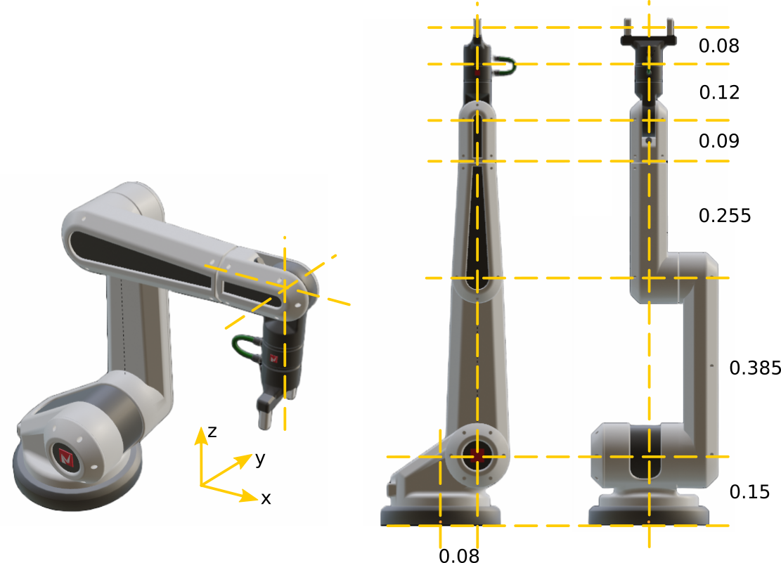
MCX-anthropomorphic-simple.xml. This mech-parameter.xml is filled in according to the figure above.
Basepose:
Define position [m] and orientation[rad] of the base.
<basepose>
    <position x ="0.0" y="0.0" z="0.0"></position>
    <orientation a="0" b="0" c="0"></orientation>
</basepose>
Segments:
Define segment number 1 till 6.
- Tip-pose position relative to previous tip pose.
- jointaxis axis of actuation for this joint one of: tran_x, tran_y, tran_z, rot_x, rot_y, rot_z.
Example:
- segment 1, Is from tip pose of the base to tip pose of link 1: x = 0.08 and y = 0.15
- segment 1, rotates around the z-axis corresponding to the rotation direction of axis 1.
  <segment number="1">
    <tippose>
        <position x ="0.08" y="0" z="0.15"></position>
    </tippose>
    <jointaxis>
      rot_z
    </jointaxis>
  </segment>
Tool-offset:
Define position [m] and orientation [rad] of the tool.
  <tool-offset name="tool1">
      <position x ="0.0" y="0.0" z="0.08">
      </position>
      <orientation a="0" b="0" c="0">
      </orientation>
  </tool-offset>
Allowable tip-pose positions:
Allowable tip-pose positions expressed in X, Y, Z. The "X" defines the allowable fill in field:
- Segment 1:
<position x ="X" y="X" z="X"></position> - Segment 2:
<position x ="X" y="0" z="X"></position> - Segment 3:
<position x ="X" y="0" z="X"></position> - Segment 4:
<position x ="0" y="0" z="X"></position> - Segment 5:
<position x ="0" y="0" z="X"></position> - Segment 6:
<position x ="0" y="0" z="X"></position>
Anthropomorphic2
The Anthropomorphic2 solver can only be used for a robotic arm with axes rotation in the following order (In stretched position):
- axis 1: rotation Z-axis
- axis 2: rotation Y-axis
- axis 3: rotation Y-axis
- axis 4: rotation Y-axis
- axis 5: rotation Z-axis
- axis 6: rotation Y-axis

Note
Axis 2, 3 and 4 should rotate around the same axis. This solver requires rotation around y axis, any other axes configuration as stated above will be unsolvable.
An example anthropomorphic2 .xml file is provided in the following link:
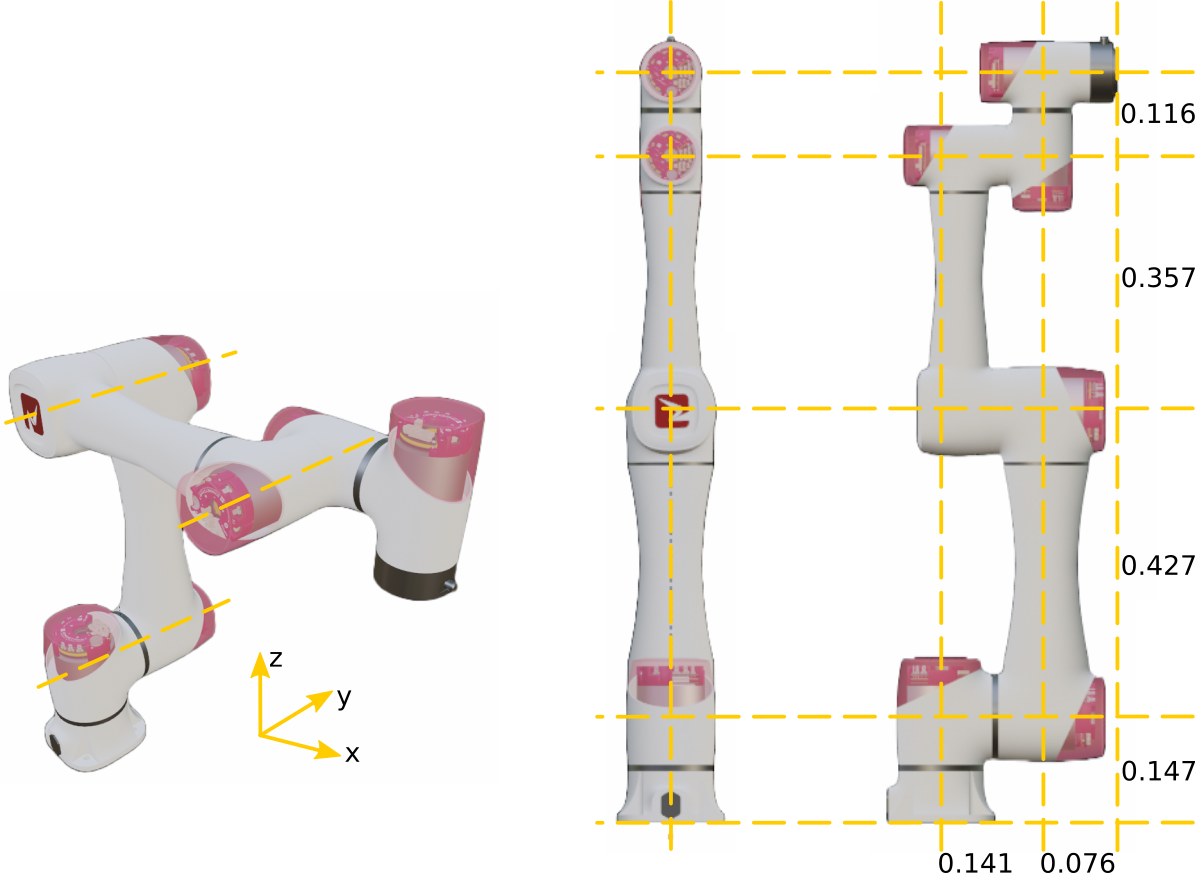
mcx-anthropomorphic2-simple.xml. This mech-parameter.xml is filled in according to the figure above.
Allowable tip-pose positions:
Allowable tip-pose positions expressed in X, Y, Z. The X defines the allowable fill in field:
- Segment 1:
<position x ="0" y="0" z="X"></position> - Segment 2:
<position x ="0" y="0" z="X"></position> - Segment 3:
<position x ="0" y="0" z="X"></position> - Segment 4:
<position x ="0" y="X" z="0"></position> - Segment 5:
<position x ="0" y="0" z="X"></position> - Segment 6:
<position x ="0" y="X" z="0"></position>
kdl_nrjl
The kdl_nrjl solver is an iterative solver and can be used for various robot arm geometries. Limitations of this solver is computing capabilities of your industrial computer used as controller. The load of you controller can be decreased, by adjusting the control_task to 500Hz (decreasing load by 50%).
An examples is provided in anthropomorphic or anthropomorphic2. Change IK solver type to (type="kdl_nrjl) and test your robot application.
Note
kdl_nrjl can be used in any axis rotation and position combination.