7 minute read
Configure Hardware in your TwinSAFE Project
In this section you will configure hardware devices in TwinCAT and Verify your TwinSAFE project. If you don’t have a project yet make sure to check out Create TwinSAFE project.
Requirements:
- TwinCAT 3 Engineering Edition on a computer (full install,including XAE shell option).
- Ethernet port on the computer (either integrated or via external USB dongle)
Create EtherCAT topology in TwinCAT
There are two ways to create a topology in TwinCAT:
- Scan for EtherCAT devices.
- Create a topology yourself by selecting components from the EtherCAT Library.
Scan for EtherCAT devices.
- Remove the EtherCAT connector from the Motorcortex controller and put it in the network adapter of the computer that runs TwinCAT.
Note
If the Motorcortex Controller is hard to reach, you can put the Controller in Bridge mode. This will force the controller to act as a bridge bewtween your Ethernet connecion and the EtherCAT connection to your EtherCAT Devices. How to set the Motorcortex controller in Bridge Mode is explained in Ethernet/EtherCAT Bridge-mode.Warning
Before scanning, make sure the dip-switches of the safety address are set to the right position on all your safety devices.- In the top bar go to
TwinCAT→Restart TwinCAT (Config Mode)

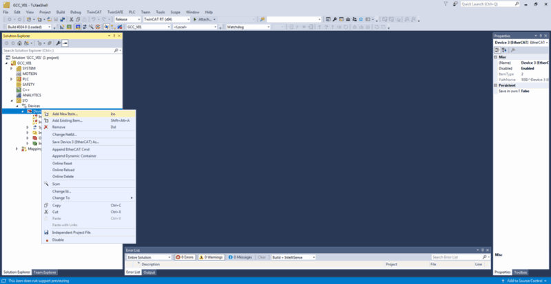
- Go to the
Solution Explorer,IO→devices, right click and selectScan.

- Next TwinCAT will show an overview of all available devices. Select the ones with
EtherCATin the name and continue.

- Next
TwinCAT Free Runhas to be activated.

- After the scan is completed, you will have an overview like below. In
Solution Explorer→Devices, you will get a folder withDevice # (EtherCAT)with in there your EtherCAT topology.

Add components from ESI Files (Optional)
If the physical devices are not available, it is also possible to create the topology yourself.
Note
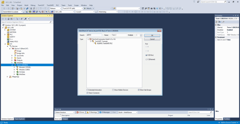
This means that the ESI files of the used components should be in the TwinCAT library. TwinCAT per default only has Beckhoff components.- In the
Solution Explorer,IO→devices, right click and selectAdd New Item. TwinCAT will show an overview of all devices it has in its library.
- Select the device you want to add. Repeat the steps above until you topology is complete.

Add physical inputs and outputs and select target system
Next step is too add the physical safe-inputs and safe-outputs that come from the EtherCAT devices. You can only do this after connecting and scanning the devices. Only the devices with Safe-Inputs/Outputs have to be added.
Select target system
select the Target System, which is another name for the Safety PLC, which is also the FSoE Master.
- In the Go to
Solution Manager,Safety→GCC_Safety_Vxxx→GCC_Safety_Vxxx Project→Target System

- Select the
Target Systemwhich is the type of safety module where the safety logic will run on. - After that, select the
Physical Device, press the `Physical Terminal for Mapping button where you select which Safety device in the EtherCAT topology will be used as Safety PLC.
 - Last make sure the
Map Serial Number&Map Project CRCandTake over Standard Alias Device namesboxes are checked.
Alias devices
Adding alias devices to the Safety project.
-
Go to
Solution Manager,Safety→GCC_Safety_Vxxx→GCC_Safety_Vxxx Project→Alias Devices→FSoE. Here are your alias devices stored. -
Right click and select
import Alias-Device.(s)

- Select the safety devices you want to add to this project.
Note
You can only select devices that have Safe Inputs/Outputs! for instance the EL 6900, EL6910 and EL6930 are Deticated logic devices these have no Safe Inputs. These are automatically the safety master.
-
In the
Solution ExplorerDouble click the added aliasdeviceand check if theFSoE safety addressis correct and linked to thePhysical Device. To take over the dip-switch address, click on therefresh icon left of the field Dip Switch and press on the green left-pointing arrow
  next to FSoE address to copy it there.
 -
Check the Linking Mode:
-
In case that safety device is not the safety PLC (FSoE master) where the project is stored, select Automatic.
-
Some Beckhoff safety devices have integrated TwinSAFE logic (e.g. EL1918), which means that you do not need an additional safety PLC (e.g. EL6910), but you can let the logic also run locally on that device. In that case, select “local” for Linking Mode.

- Check the connection tab:
- Some Beckhoff safety devices have integrated TwinSAFE logic (e.g. EL1918), which means that you do not need an additional safety PLC (e.g. EL6910), but you can let the logic also run locally on that device. This example has Inputs that have to mapped. make sure you check the info data you want to read out with Motorcortex on these devices.

Creating signals for communication with Motorcortex
It is possible to send data to and receive data from the Safety PLC. This can be done via so-called standard variables. These signals will also be available to Motorcortex.
-
In the Solution Explorer,
Solution Manager,Safety→GCC_Safety_Vxxx→GCC_Safety_Vxxx Project→StandardDatayou will find theFromSafetyPLC(For Outputs) &ToSafetyPLC(For Inputs) folders. -
Right click the folder you want to add a in/output and to Choose the option
Add multiple standard variables.

-
It is important to keep track of the order of the variables, since otherwise they might be in the wrong order in Motorcortex. If you delete a variable, all will shift one up. It is not possible to add a new one and rename it.
Remark: The variable mapping should be done in the same Order as twinCAT IO/Devices./../Term X(EL6910)/../StandardInputs_Outputs mapping.
| Name | Order in TwinCAT | Order in Motorcortex |
|---|---|---|
| i00ErrorAcknowledgement.sds | Input byte 0, bit 0 | Output byte 0, bit 0 |
| i01Run.sds | Input byte 0, bit 1 | Output byte 0, bit 1 |
| i02NoEstop.sds | Input byte 0, bit 2 | Output byte 0, bit 2 |
| i03WatchdogPulse.sds | Input byte 0, bit 3 | Output byte 0, bit 3 |
| i04WatchdogPulse.sds | Input byte 0, bit 4 | Output byte 0, bit 4 |
| Name | Order in TwinCAT | Order in Motorcortex |
|---|---|---|
| o00STONotActive.sds | Output byte 0, bit 0 | Input byte 0, bit 0 |
| o01SWEStopOk.sds | Output byte 0, bit 1 | Input byte 0, bit 1 |
| o02WatchdogOk.sds | Output byte 0, bit 2 | Input byte 0, bit 2 |
| o03EStopButtonsOK.sds | Output byte 0, bit 3 | Input byte 0, bit 3 |
| o04InRun.sds | Output byte 0, bit 4 | Input byte 0, bit 4 |
| o05FBErr.sds | Output byte 0, bit 5 | Input byte 0, bit 5 |
| o06ComErr.sds | Output byte 0, bit 6 | Input byte 0, bit 6 |
| o07ItherErr.sds | Output byte 0, bit 7 | Input byte 0, bit 7 |
| o08ComStartUp.sds | Output byte 1, bit 1 | Input byte 1, bit 1 |
| o09FBDeactive.sds | Output byte 1, bit 2 | Input byte 1, bit 2 |
| o10FBRun.sds | Output byte 1, bit 3 | Input byte 1, bit 3 |
Note
Take note in the table above that all in/outputs are numbered in their name by their byte and because a Byte cannot exceed 8 bits. the byte goes up by 1 increment. This is very important for later configuring the Motorcortex ethercat.Variable Mapping
The last step is to link the signals of your TwinSafeGroup(Safety program) to the hardware or standard variables.
-
go to
Solution Manager,Safety→GCC_Safety_Vxxx→GCC_Safety_Vxxx Project→TwinSafeGroupgroup Next step is to define names to signals in theTwinSafeGroup1.saiNaming can be done by clicking on left of the input or right output and by starting to type. -
go in the top bar to
view→Other Windows→Variable Mapping.

- in the lower menu you wil see the
Variable Mappingmenu appear. In this menu you can link your hardware or standard variables to yourTwinsafe Group

- Start linking the variables to the inputs and outputs. If an variable cannot be found, it might already be used: click on “Used and unused” to find it.In order to link multiple inputs/outputs to a variable, use the Ctrl button.

Verify project
Last step is to go to TwinSAFE → Verify Complete Safety Project.

Typical errors are:
- Dip-switches not matching the FSoE address (set the correct values)
- Double used FSoE addresses (set the correct values)
- Target system not reachable/not found in case your EtherCAT devices are not connected (connect TwinCAT to the EtherCAT devices again)
Note
In the Vectioneer generic template, you will always get warnings: The parameter value of “Safe Inputs After Disc Error” of …. is always true in this selected target system logic.". This is correct and the motivation for it can be found in Vectioneer User Defined Function BlocksThe next step is to download the safety project to your Safety PLC. There are 2 ways to do this: Using Twincat Download TwinSAFE project to FSoE Master with TwinCAT or via the TwinSAFE Loader. Download TwinSAFE project to FSoE Master with TwinSAFEloader.